
23-1
Diesel Turbo Direct Injection
(TDI) system, servicing
The Diesel Direct Fuel Injection (DFI) Engine
Control Module (ECM) is equipped with
Diagnostic Trouble Code (DTC) memory.
Before starting repairs, adjustments and/or
troubleshooting:
- Check DTC memory for possible stored
Diagnostic Trouble Codes (DTCs)
page 01-
15
.
- Check Diesel DFI ECM output signals to
components using output Diagnostic Test Mode
(DTM)
page 01-51
.
During checking and adjusting procedures, the
Diesel DFI ECM may recognize malfunctions and
store DTCs.
For this reason, after completing all checking and
adjusting procedures, you must:
- Check and erase DTC memory
page 01-
41
.
- Re-create readiness code
page 01-47
.

23-2
Safety precautions
WARNING!
Fire hazard! Do not have anything in the area
that can ignite Diesel fuel. To guard against
personal injury, and damage to vehicle
components.
Be sure the ignition is switched OFF, when:
Disconnecting or connecting Diesel fuel
injection and glow plug system wiring or test
equipment
Disconnecting the battery
BEFORE cranking the engine at starting RPM
(such as for compression testing):
Disconnect the harness connector for fuel
cut-off valve -N109- on the Diesel injection
pump.
After the work is completed, check and erase
Diagnostic Trouble Code (DTC) memory.
CAUTION!

BEFORE disconnecting (or connecting) the
battery:
Be sure the ignition is switched OFF. Failure
to do so may damage the Diesel Direct Fuel
Injection (DFI) Engine Control Module (ECM).
Be sure of the proper radio code (for vehicles
equipped with coded anti-theft radio).
23-3
Rules for cleanliness
CAUTION!
When working on the fuel supply or Diesel
injection system, always observe the
following rules of cleanliness.
1. Thoroughly clean fuel system line and hose
connections and the surrounding area before
disconnecting.
2. Place removed components on a clean
surface and cover. Use plastic sheet or paper.
Do not use fluffy rags that leave lint!
3. Carefully cover over or seal any components
that have been opened if repairs are not carried
out immediately.
4. Install only clean parts:
Do not remove replacement parts from the
packaging until immediately before they are to
be installed.
Do not use parts that have been stored without
packaging (e.g. in toolboxes, etc.).
5. When the fuel system has been opened, avoid

working with compressed air whenever possible,
and also avoid moving the vehicle if possible.
6. Do not let Diesel fuel come in contact with
engine coolant hoses and, if necessary,
immediately clean any hose that has been
contaminated by fuel. Replace hoses if Diesel
fuel has had time to soak into the hose material.
23-4
Diesel Direct Fuel Injection (DFI) system
components, overview
Components -A- through -D- below are not shown
in the illustration.
A - Brake light switch -F-, Brake vacuum
vent valve switch -F47-
Combined into one assembly in footwell on
brake pedal
B - Throttle Position (TP) sensor -G79-
In footwell, on accelerator pedal
page
23-13
Displayed as "Throttle position sensor-
G69" in case of malfunction
C - Clutch vacuum vent valve switch -F36-
In footwell, on clutch pedal
D - Barometric pressure (BARO) sensor -
F96-
Internal component of Diesel DFI Engine
Control Module (ECM) -J248-
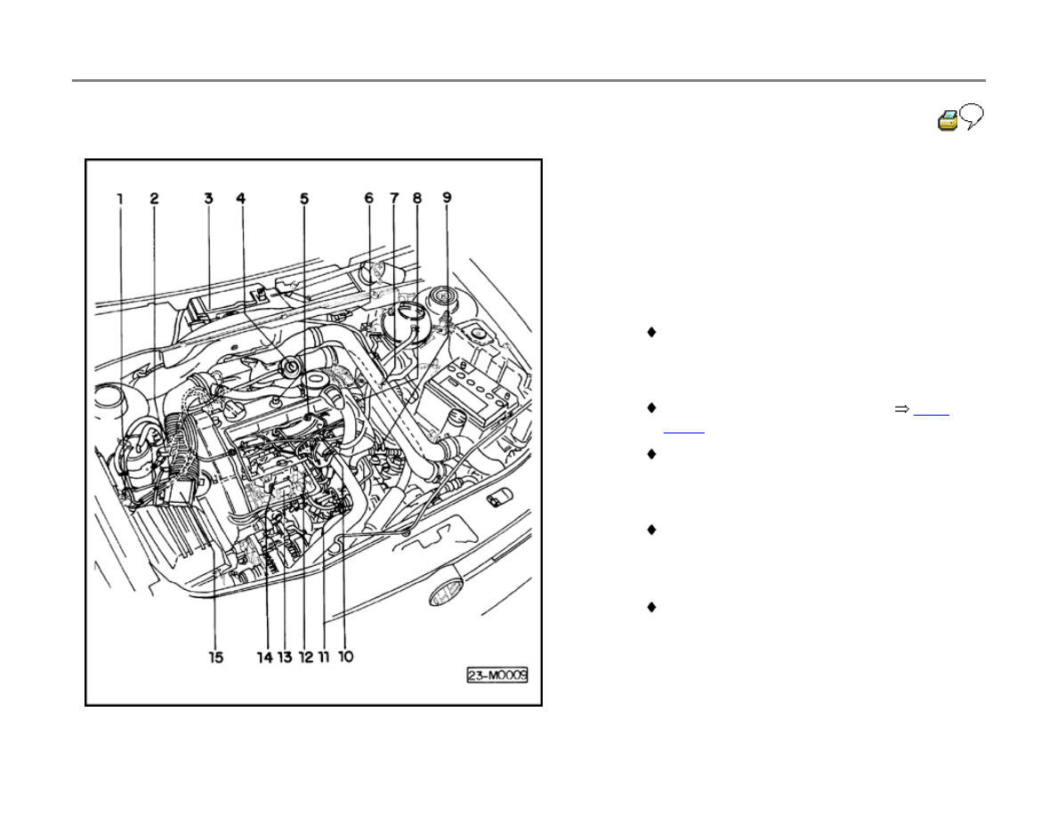
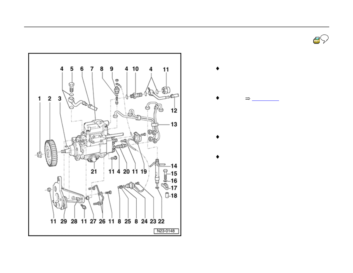
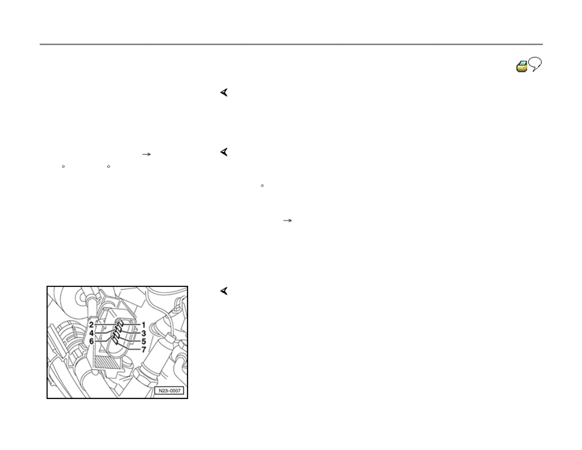
23-5
1 - Wastegate bypass regulator valve -N75-
2 - EGR vacuum regulator solenoid valve -
N18-
3 - Diesel Direct Fuel Injection (DFI) Engine
Control Module (ECM) -J248-
With Manifold Absolute Pressure (MAP)
sensor -G71-
With Barometric Pressure (BARO) sensor -
F96-
4 - Exhaust Gas Recirculation (EGR) valve
5 - Fuel injector
With needle lift sensor -G80-
6 - Coolant glow plug relay -J325-
7 - Intake Air Temperature (IAT) sensor -G72-
8 - Harness connector
For needle lift sensor -G80-
9 - Harness connector
For engine speed (RPM) sensor -G28-
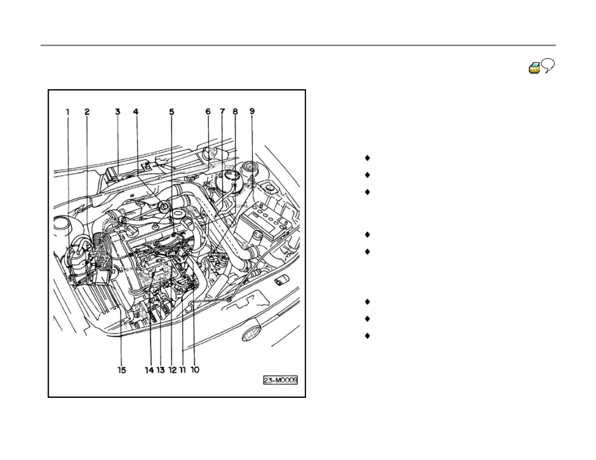
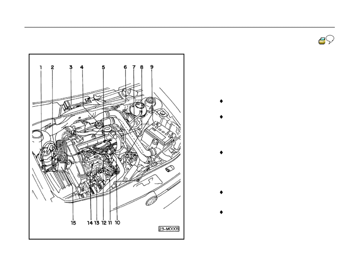
23-6
10 - Engine Coolant Temperature (ECT) sensor
-G62-
11 - Central harness connector
For:
Fuel temperature sensor -G81-
Quantity adjuster -N146-
Modulating piston displacement sensor -
G149-
12 - Harness connector
For fuel cut-off valve -N109-
For cold start injector -N108-
13 - Injection pump quantity adjuster
With:
Fuel temperature sensor -G81-
Quantity adjuster -N146-
Modulating piston displacement sensor -
G149-
14 - Fuel cut-off valve -N109-
15 - Mass Air Flow (MAF) sensor -G70-
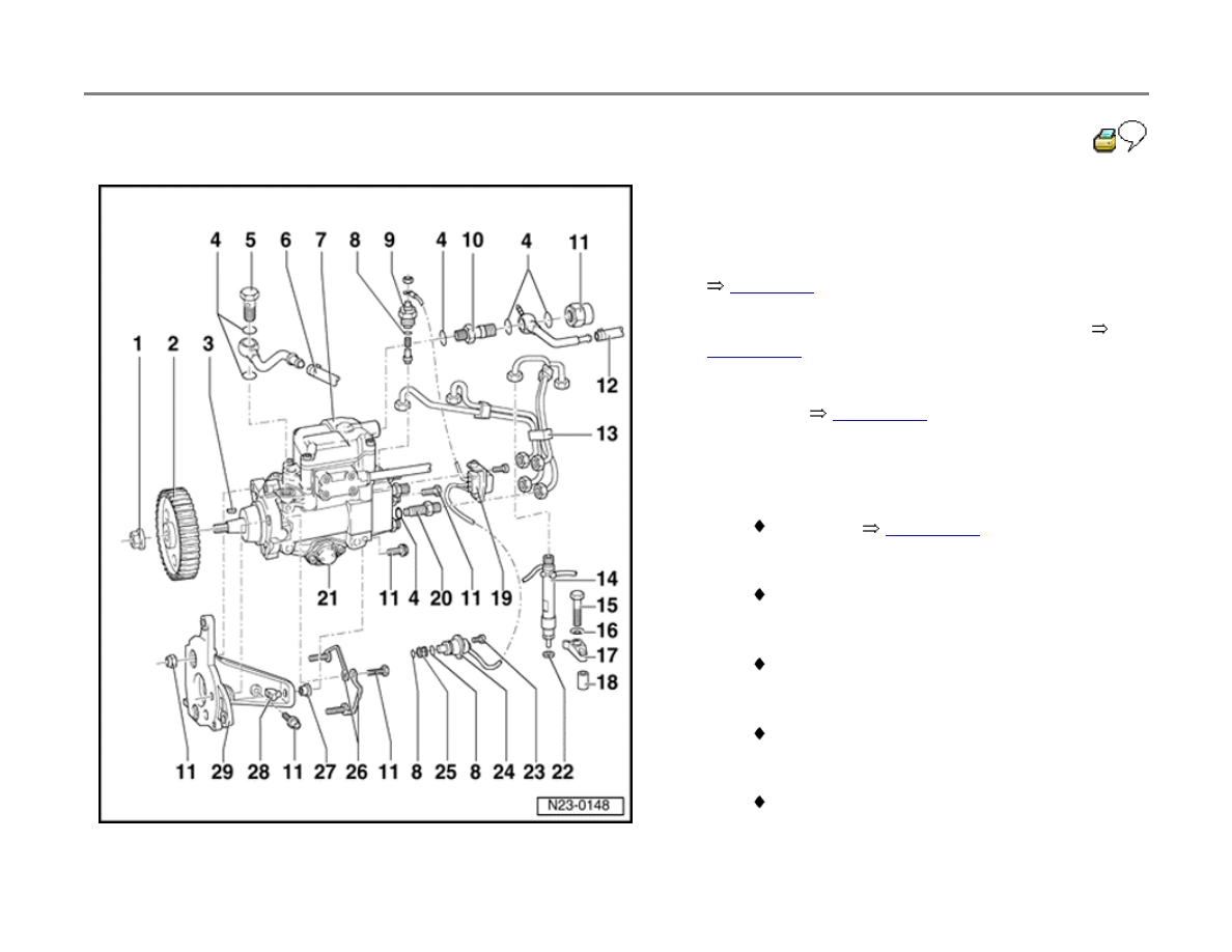
23-7
Diesel injection pump, servicing
Refer to Rules for cleanliness.
page 23-3
Diesel injection pump, removing and installing
page 23-18
.
Diesel injection pump, checking and adjusting
dynamically
page 23-23
.
1 - 55 Nm (41 ft lb)
2 - Injection pump sprocket
Removing
page 23-19
3 - Woodruff key
Make sure it fits securely
4 - Oil seal
Always replace
5 - Banjo bolt
25 Nm (18 ft lb)
6 - Supply hose
From fuel filter
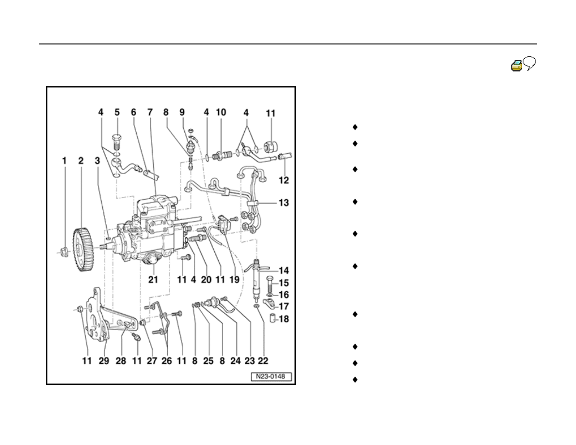
23-8
7 - Injection pump
With:
Quantity adjuster -N146-
Modulating piston displacement sensor -
G149-
Fuel temperature sensor -G81-
8 - O-ring
Replace if damaged
9 - Fuel cut-off valve
40 Nm (30 ft lb)
10 - Union
For return line
11 - 25 Nm (18 ft lb)
12 - Return hose
To control valve/fuel filter
13 - Injector lines
25 Nm (18 ft lb)
Remove using 3035 tubing wrench
Always remove injector lines as an
assembly

Do not bend or otherwise alter shape
23-9
14 - Fuel injector
For 3rd cylinder with needle lift sensor
Removing and installing
page 23-29
Servicing
page 23-31
15 - 20 Nm (15 ft lb)
16 - Dished washer
17 - Retainer
18 - Mounting
19 - 3-pin harness connector
For fuel cut-off valve and cold start injector
20 - Union
With pressure valve
45 Nm (33 ft lb)
21 - Timing control cover
If leaking, replace O-ring
page 23-33
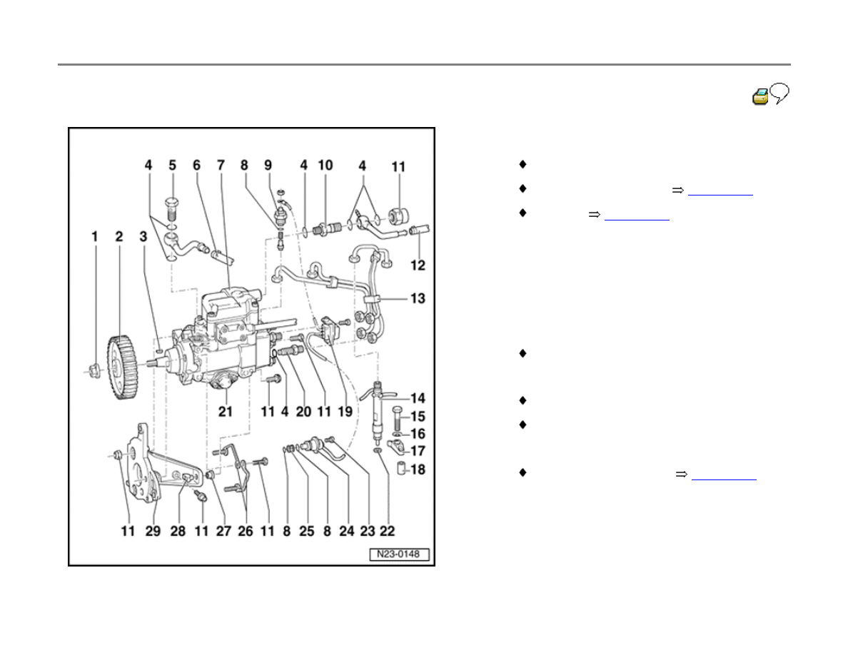
23-10
22 - Heat shield
Always replace
23 - 10 Nm (7 ft lb)
24 - Cold start injector N108
Checking
page 01-51
25 - Strainer
26 - Retainer
27 - Sleeve
Tapered
28 - 25 Nm (18 ft lb)
Nut with taper
29 - Console
23-11
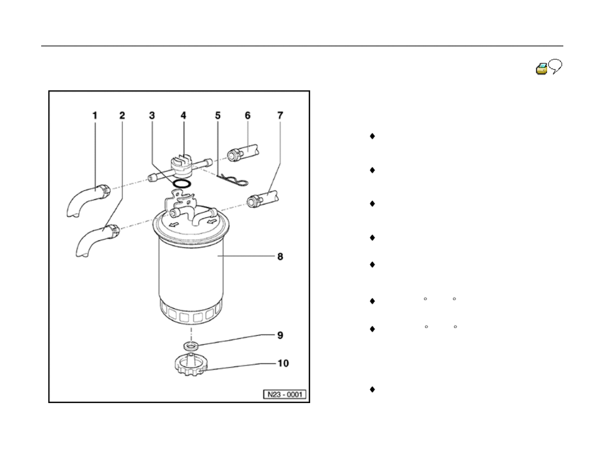
Fuel filter, servicing
1 - Return line
From Diesel injection pump
2 - Supply line
To Diesel injection pump
3 - O-ring
Always replace
4 - Control valve
Installed position: arrow points towards fuel
tank
When changing filter, remove retaining clip
and control valve as an assembly
(complete with fuel lines)
Below +15 C (59 F): passageway to filter
is open
Above +31 C (88 F): passageway to filter
is closed
5 - Retaining clip
6 - Return line
To fuel tank
7 - Supply line

From fuel tank
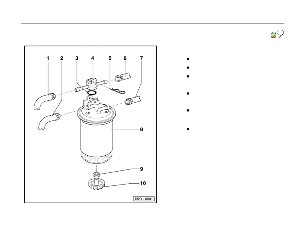
23-12
8 - Fuel filter
Arrow marks direction of flow
Do not interchange connections
Replace if damaged
9 - Gasket
Replace if damaged
10 - Water drain plug
To bleed, remove mounting clip and control
valve as a complete assembly (with fuel
lines attached)
Loosen and allow fluid to drain (approx.
100 cc or 3-4 fl. oz.)
23-13
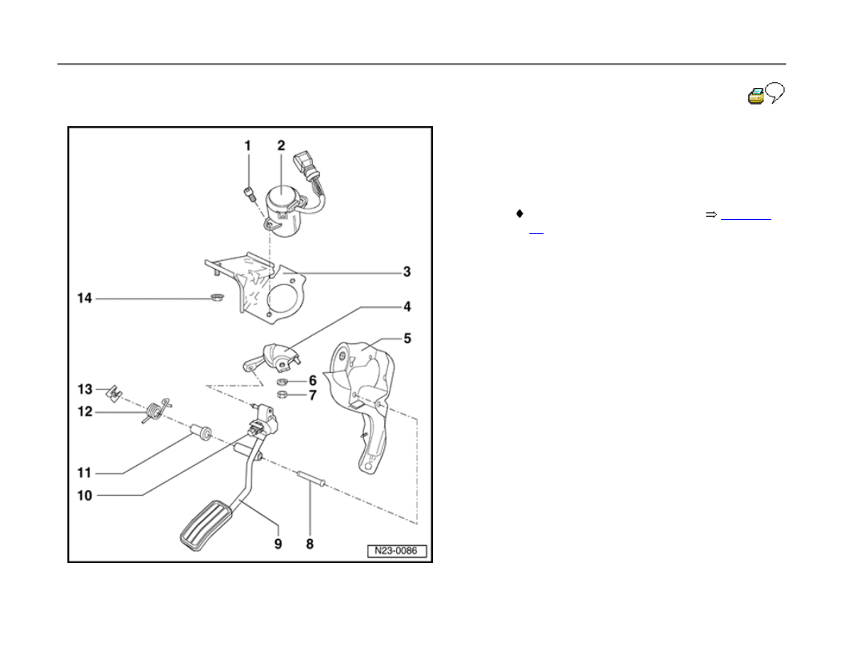
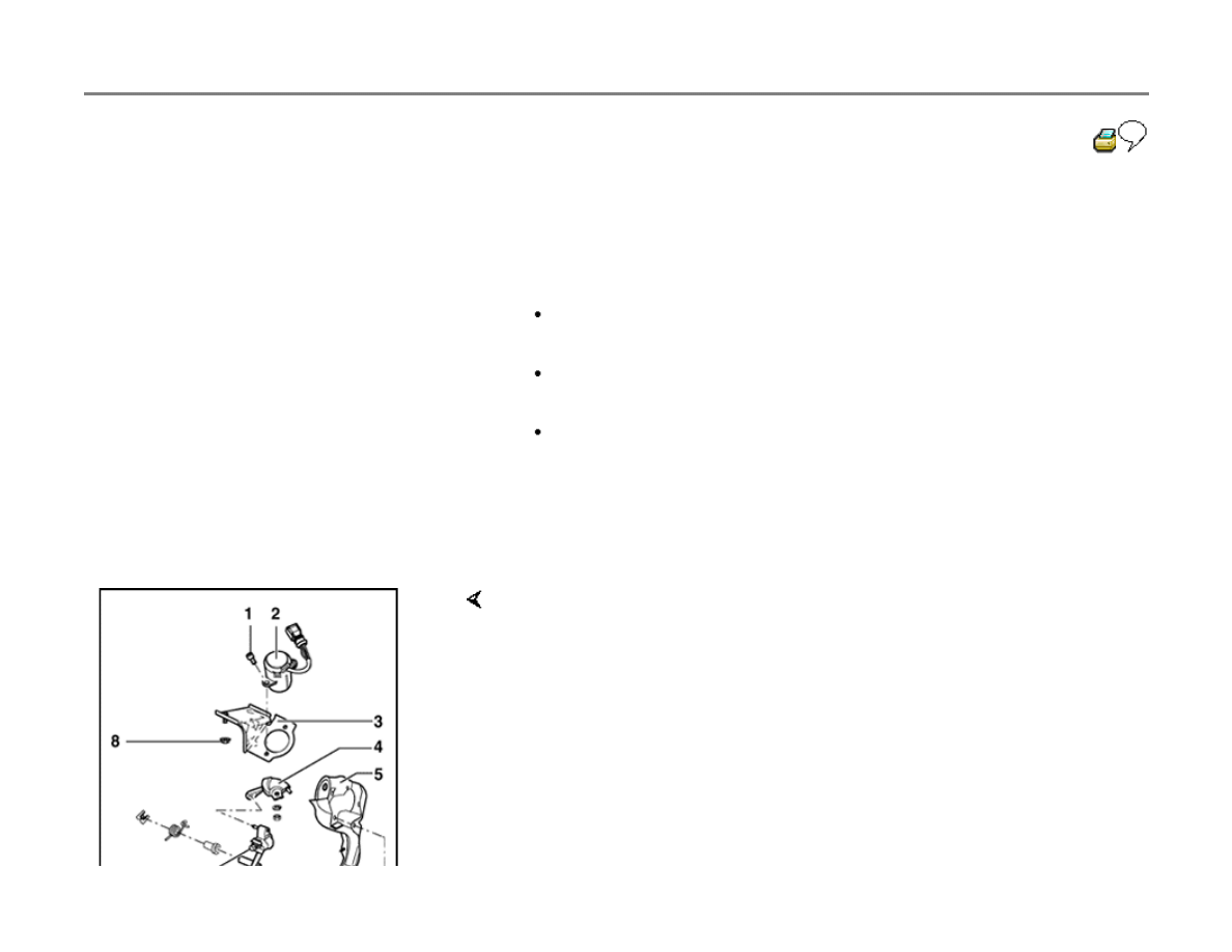
Accelerator pedal control, servicing
1 - 10 Nm (7 ft lb)
2 - Throttle Position (TP) sensor -G79-
Removing, installing, adjusting
page 23-
15
3 - Bracket
4 - Cable cam
5 - Mounting pedestal
6 - Spring washer
7 - 10 Nm (7 ft lb)
8 - Pivot pin
9 - Accelerator pedal
10 - Adjustment bolt
11 - Bushing
12 - Torsion spring
13 - Circlip
14 - 20 Nm (15 ft lb)
23-14
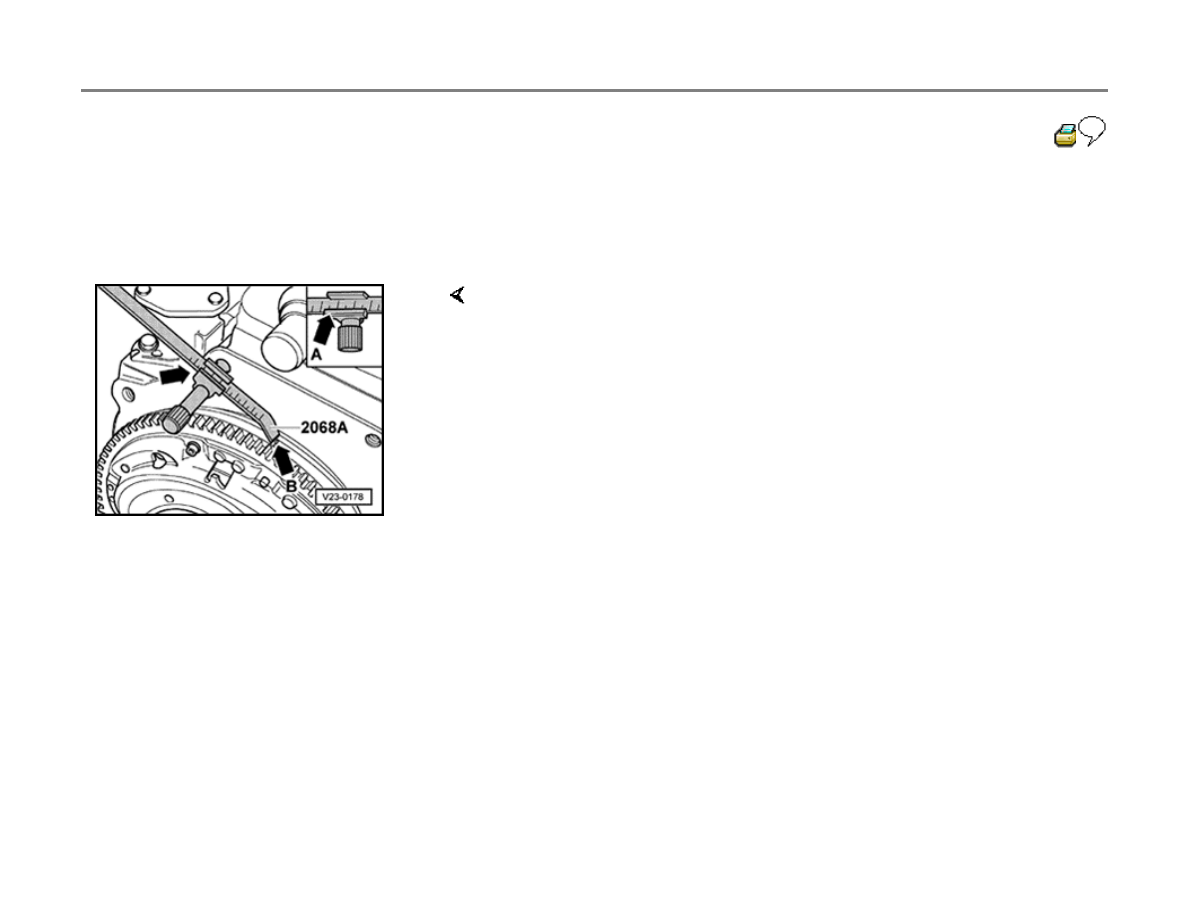
Cylinder 1 at Top Dead Center (TDC),
setting
(Engine removed)
- Attach adjusting gauge 2068A as shown.
- Set adjusting gauge to 96.0 mm.
Refer to marking on left of vernier scale (arrow -A-).
- Rotate crankshaft until TDC mark on flywheel is aligned with tip of
adjusting gauge (arrow -B-).
23-15
Throttle Position (TP) sensor, removing,
installing and adjusting
Special tools, testers and auxiliary items
VAG1551 or VAG1552 Scan Tool (ST)
VAG1551/3 adapter cable
Box wrench, e.g. Hazet 4561
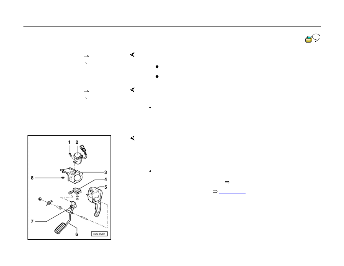
Removing
- Remove instrument panel and pedal cluster
cover.
Installing
- Remove accelerator pedal -6-.
- Remove throttle position sensor -2- with bracket -3-, by removing both
mounting nuts -8- with 1/4-in. drive tools.
- Remove cable cam -4- and unscrew sensor from bracket.
- Secure throttle position sensor to bracket.
- Attach cable cam to sensor.
23-16
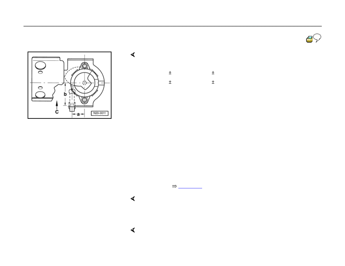
Note:
The cable cam eye must be parallel to the forward direction.
Adjusting
- Check attachment to make sure that dimensions -a- and -b- are as
specified when facing forward (arrow -c-).
a = 22 0.05 mm (0.866 0.002 in.)
b = 41 0.05 mm (1.614 0.002 in.)
- Install sensor with bracket.
- Install accelerator pedal cable and mount cable cam eye to pin on
accelerator pedal.
- Connect VAG1551 or VAG1552 scan tool.
- Switch ignition on.
- Press buttons -0- and -1- to insert the "Engine Electronics" address
word 01
page 01-9
.
Rapid data transfer
HELP
Select function XX
Indicated on display
- Press buttons -0- and -8- to select "Read Measuring Value Block"
function 08, and press -Q- button to confirm input.
Read Measuring Value Block
HELP
Indicated on display

Input display group number XXX
- Press buttons -0-, -0- and -2- to input display group no. 2 (002), and
press -Q- button to confirm input.
23-17
Read Measuring Value Block 2
0 rpm 0.0 % 0 1 0 18.4
C
- Check throttle position in display field 2.
Accelerator pedal not depressed (at rest position)
Specification: 0.0 %
Read Measuring Value Block 2
0 rpm 0.0 % 0 1 0 18.4
C
If necessary, adjust throttle position as follows:
- Fully (slowly) depress accelerator pedal while watching value in display
field 2.
Throttle position value must increase continuously and then display
100% just before Wide Open Throttle (WOT) stop.
- Turn adjustment screw -7- until Closed Throttle Position (CTP) display
shows 0.0 %.
- Depress accelerator pedal to point just before Wide Open Throttle
(WOT).
Display must show 100 %
- Check and erase DTC memory
page 01-41
.
- Re-create readiness code
page 01-47
.

23-18
Diesel injection pump, removing and
installing
WARNING!
Fire hazard! Do not have anything in the area
that can ignite Diesel fuel.
Special tools, testers and auxiliary items
2064 lock pin
2065A setting bar
3032 puller
3035 injector line wrench
V159 pin wrench
Torque wrench (VAG1331 or equivalent)-5 to
50 Nm (approx. 40 ft lb)
Removing
-
Remove air cleaner and upper toothed belt
guard.
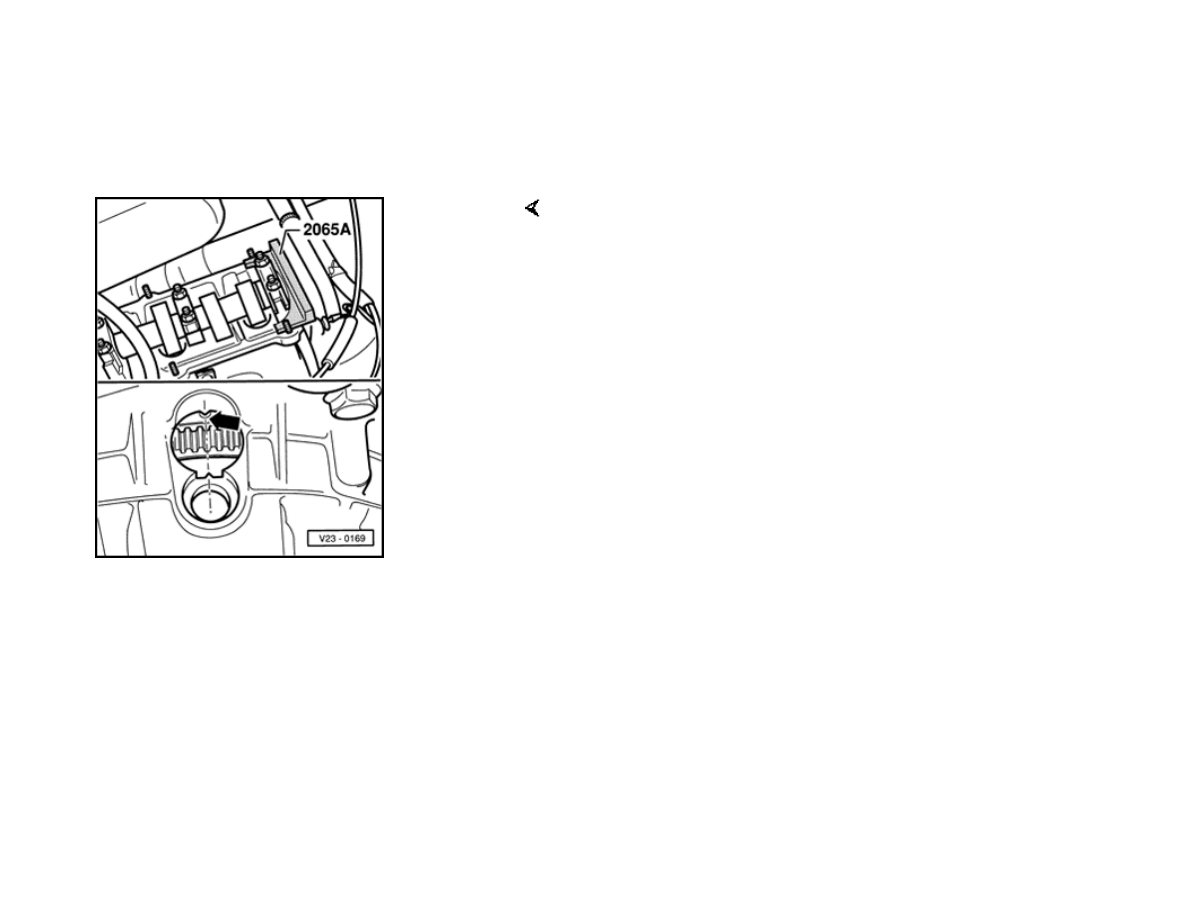
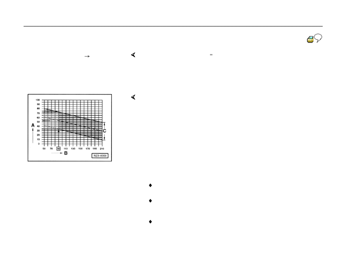
- Remove cylinder head cover.
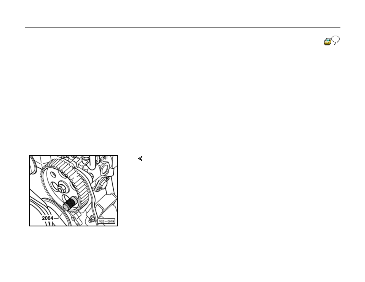
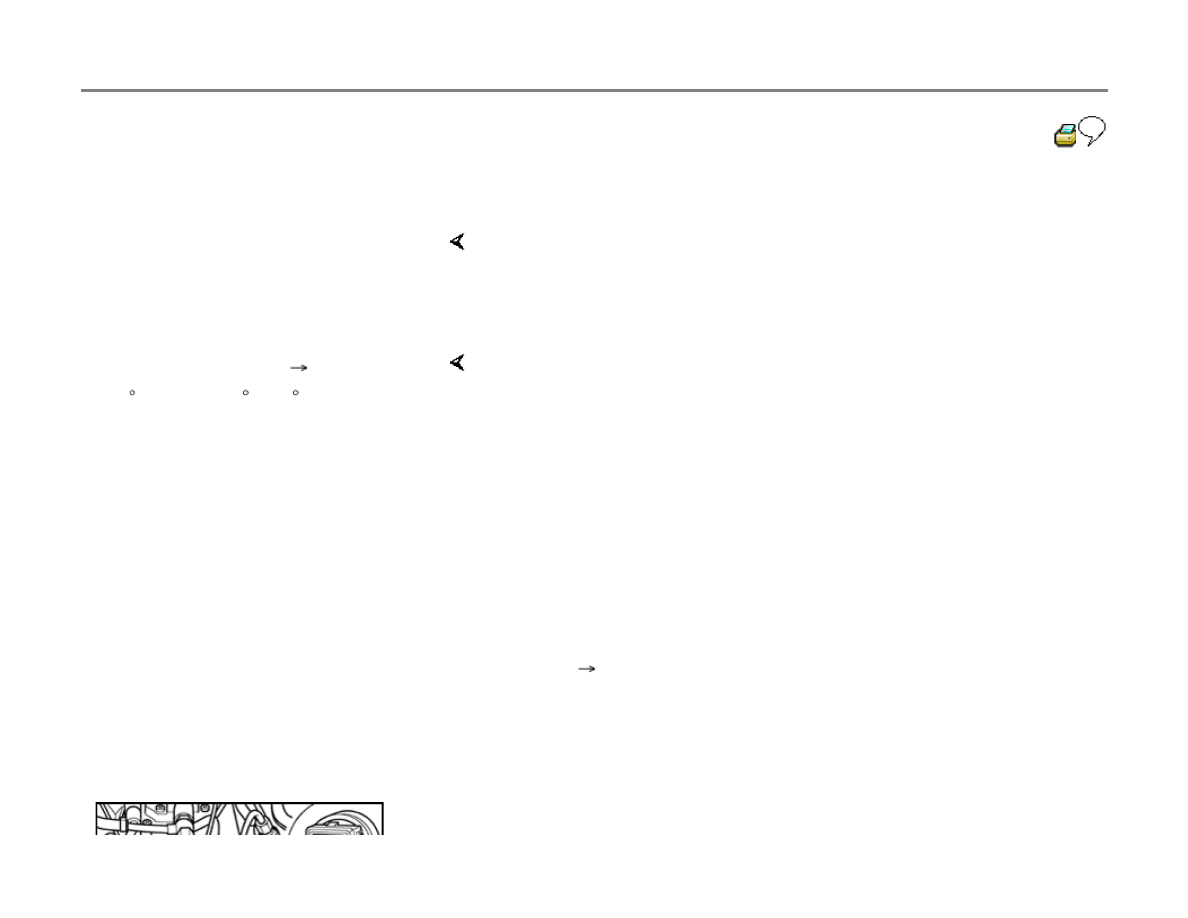
- Rotate crankshaft to TDC for cylinder 1 (arrow).
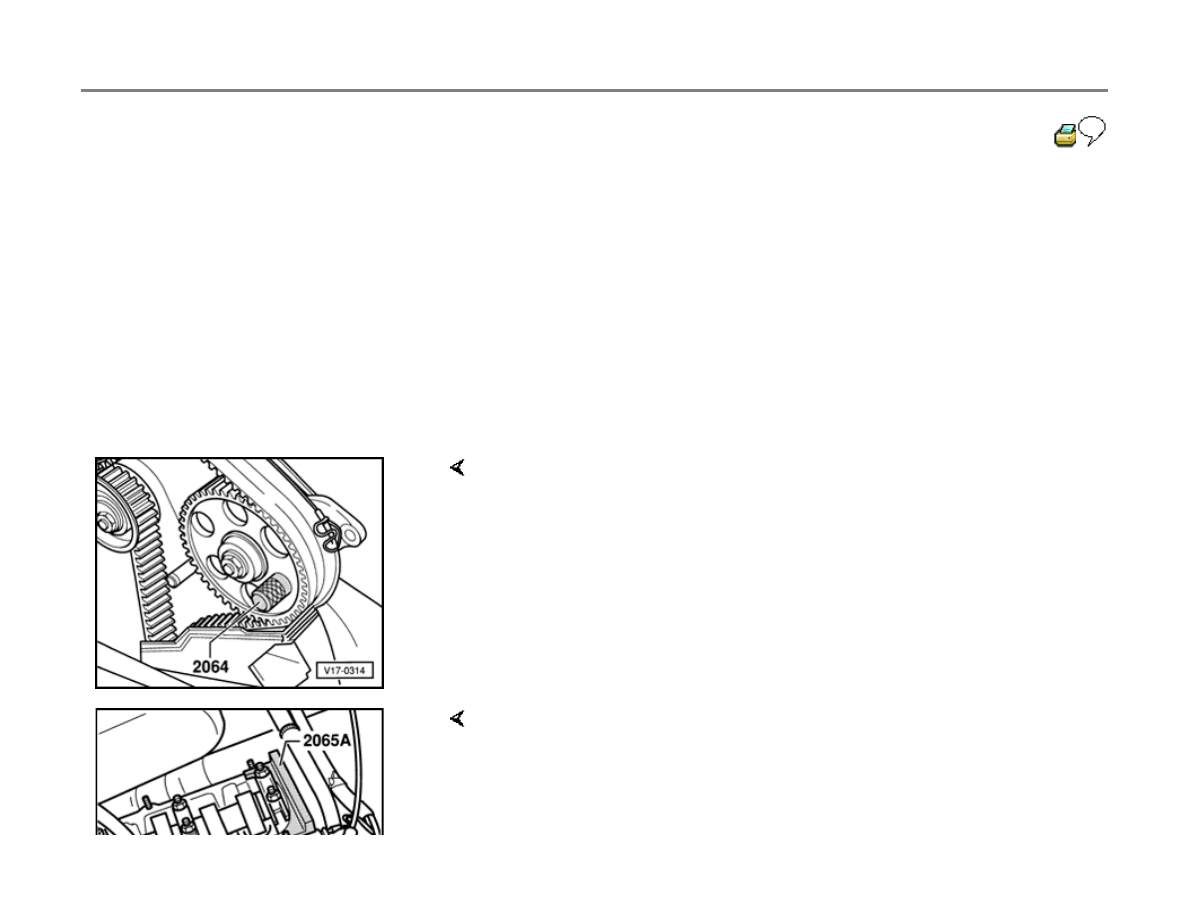
- Lock camshaft with 2065A setting bar.

23-19
- Position camshaft with 2065A setting bar as
follows:
- Turn camshaft until one end of bar contacts
cylinder head, then use feeler gauge to
measure gap at other end of bar.
- Place another feeler gauge (thickness = 1/2
measured gap) between setting bar and
cylinder head.
- Turn camshaft until setting bar contacts feeler
gauge, then place another feeler gauge of
equal thickness at other side, between setting
bar and cylinder head.
- Remove idler roller, remove nut from tensioner
roller, and release tension of toothed drive belt.
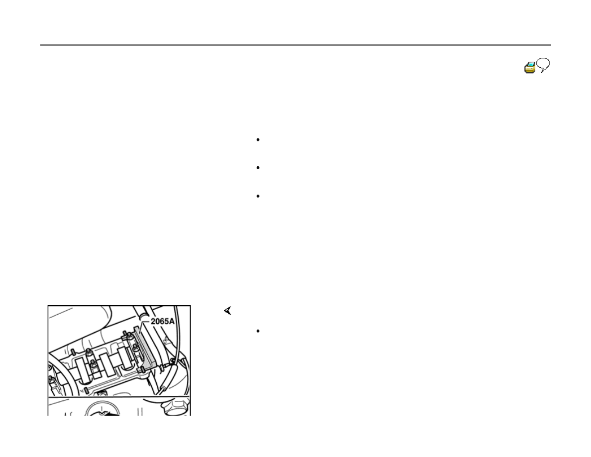
- Remove belt from sprockets, and lock Diesel injection pump sprocket
in position using lock pin 2064.
- Remove injection pump sprocket mounting nut.
- Loosen arms of 3032 puller, place arms in position through holes in
injection pump sprocket, and tighten.
- Place injection pump sprocket under tension with puller.
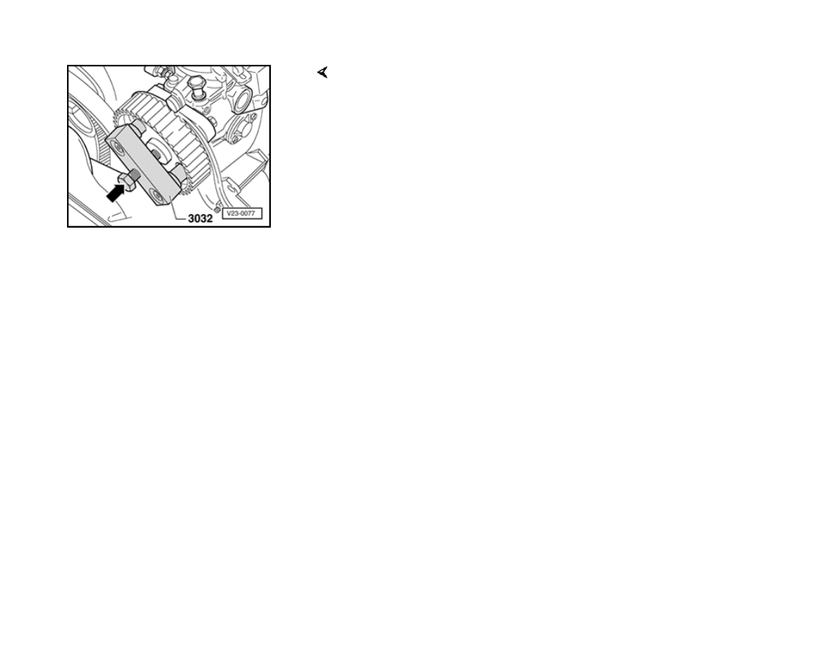
- Hold onto sprocket and tap lightly on puller spindle to release sprocket
from injection pump tapered shaft (arrow).
23-20
- Unbolt all fuel lines at fuel pump
Note:
Use 3035 tubing wrench to remove high pressure
fuel lines.
- Cover openings with clean lint free cloth
- Disconnect fuel cut-off valve/cold start injector
connector.
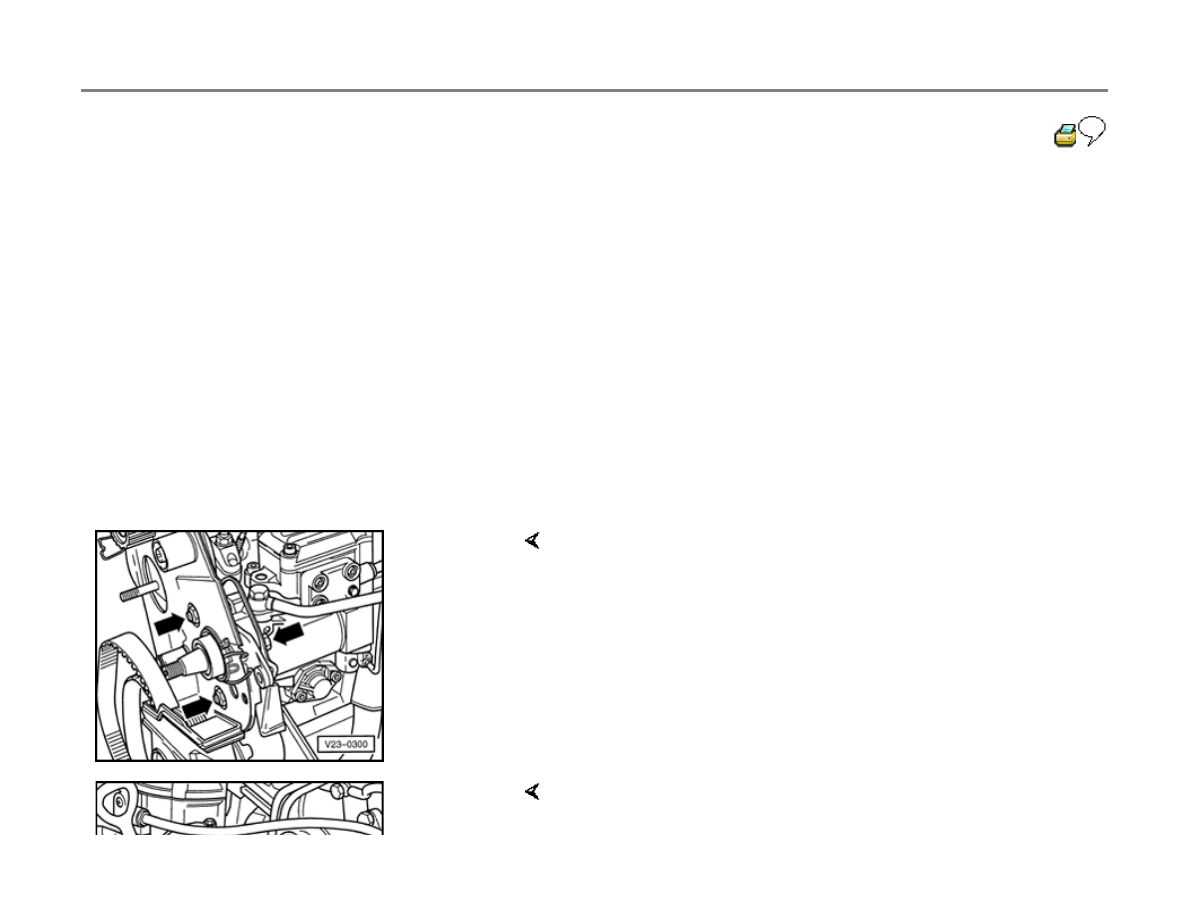
- Disconnect quantity adjuster harness connector
and unclip connector retainer.
- Remove mounting bolts from bracket -arrows-
- Remove bolt from rear support (arrow).

- Remove Diesel injection pump.
23-21
Installing
- Insert injection pump into bracket and then
tighten mounting bolt on rear support with
conical nut first.
- Align so injection pump is centered in elongated
holes in bracket, and hand-tighten in this
position.
Note:
Adjust start of injection dynamically using
VAG1551 scan tool.
- Install injection pump sprocket and lock into position using 2064 lock
pin. Make sure spring washer is correctly seated.
- Tighten mounting nut.
Tightening torque: 55 Nm (41 ft lb)
- Loosen camshaft sprocket mounting bolt 1/2-turn.
- Place drift through hole in rear belt guard, tap carefully with hammer to
release sprocket from tapered end of camshaft, and remove camshaft
sprocket.
- Check to make sure that TDC mark on flywheel and reference mark on
transmission housing are aligned.
- Place belt on injection pump sprocket and tensioner roller.

- Install camshaft sprocket on toothed belt and secure sprocket so
camshaft can still turn.
- Install idler roller.
23-22
- Remove locking pin from injection pump
sprocket.
page 23-23
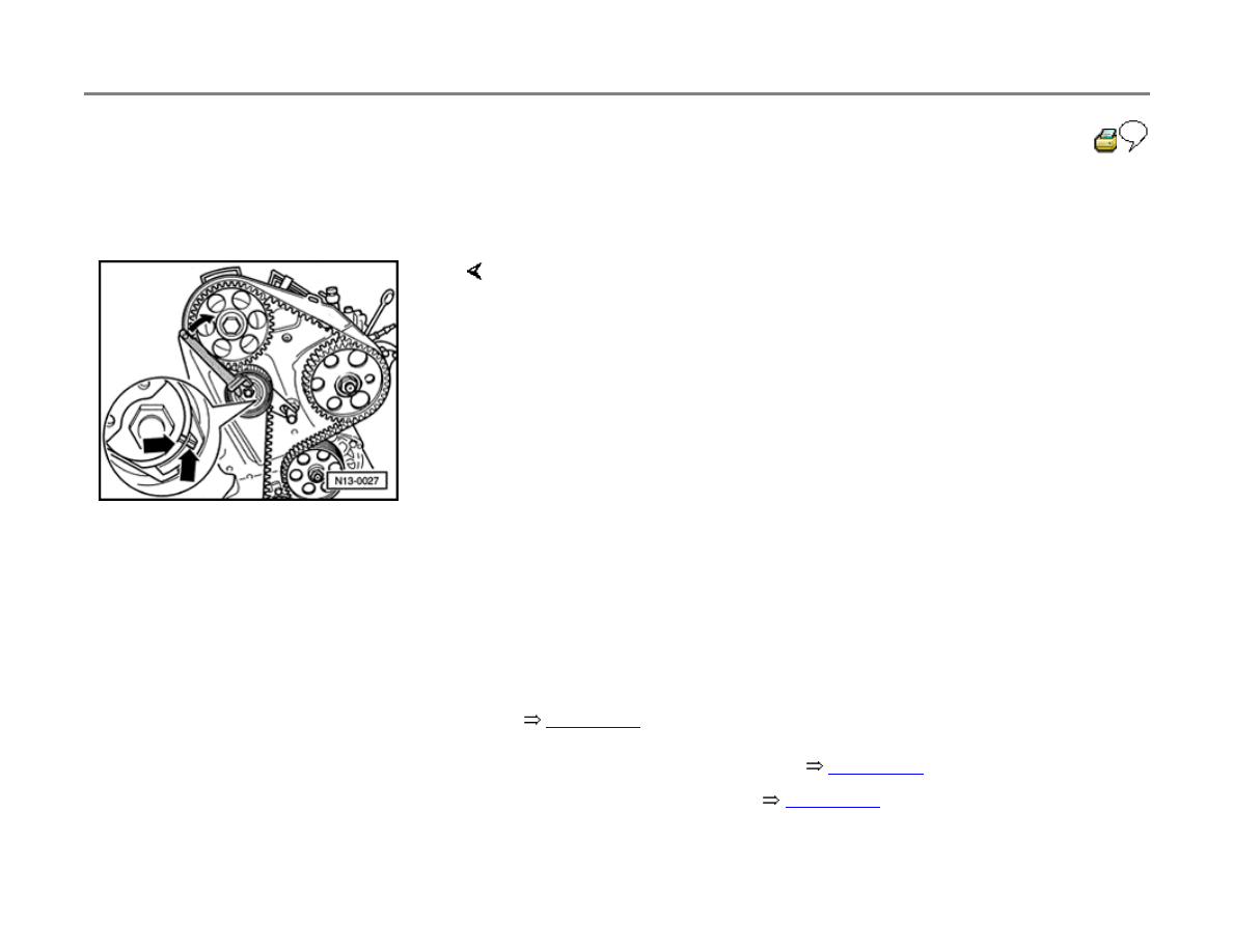
- Adjust toothed belt tension using pin wrench on eccentric (e.g. Matra
V159); turn clockwise until notch and raised mark (arrows) are aligned.
- Tighten mounting nut.
Tightening torque: 20 Nm (15 ft lb)
- Check TDC mark on flywheel again.
- Tighten camshaft sprocket mounting bolt.
Tightening torque: 45 Nm (33 ft lb)
- Remove 2065A setting bar from camshaft.
- Fill injection pump with clean Diesel fuel through return line union.
New pump fill quantity: 180 ml minimum
- Re-connect injector lines, fuel lines and wiring.
- Install belt guard, cylinder head cover and air cleaner.
- Dynamically check start of injection and adjust if necessary.
- Check and erase DTC memory
page 01-41
.
- Re-create readiness code
page 01-47
.
23-23
Start of injection, dynamically checking
and adjusting
Dynamically checking and correcting start of
injection is only possible using "Basic Setting"
scan tool function 04.
Note:
Start of injection must always be checked and
adjusted after:
Replacing the toothed belt
Loosening the Diesel injection pump mounting
bolts
Loosening the toothed belt sprockets
Special tools, testers and auxiliary items
VAG1551 or VAG1552 Scan Tool (ST)
VAG1551/3 adapter cable
3035 injector line wrench

Torque wrench (VAG1331 or equivalent)-5 to
50 Nm (approx. 40 ft lb)

23-24
Checking and adjustment conditions
Mechanical engine basic settings OK
Toothed belt tension OK
Checking
- Connect VAG1551 or VAG1552 scan tool
page 01-9
.
- Start engine and let idle.
- Press buttons -0- and -1- to insert the "Engine
Electronics" address word 01.
Rapid data transfer
HELP
Select function XX
Indicated on display
- Press buttons -0- and -4- to select "Basic Setting" function 04.
- Press -Q- button to confirm input.
Basic Setting
HELP
Input display group number XXX
Indicated on display
- Press -0- button three times to input display group no. 0 (000).
- Press -Q- button to confirm input.
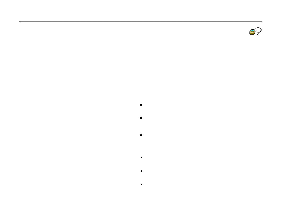
23-25
System in Basic Setting
1 2 3 4 5 6 7 8 9 10
Indicated on display (1-10
display fields)
Note:
The start of injection value in display field 2 varies depending on the fuel
temperature value in display field 9.
Example:
The fuel temperature value "B" in display field 9 (e.g. 90) corresponds to
the start of injection value "A" in display field 2, which should fall within the
range "C" between 34 and 73.
Notes:
A - Display field 2-Start of injection value
B - Display field 9-Fuel temperature value
C - Specified range for start of injection
(depending on fuel temperature)
If, when checking the start of injection, the results fall within zone -C-,
no adjustment is required.
After repairs e.g. removing and installing Diesel injection pump, set
the start of injection to the mean value (dashed line) of the specified
zone -C-.
If the start of injection is too far advanced, adjust by turning the
injection pump in the direction of engine rotation.

If start of injection is too far retarded, adjust by turning the injection
pump against the direction of engine rotation.

23-26
- Loosen Diesel injection pump mounting bolts
approx. 1 turn, but leave easiest-to-reach bolt
until last.
- Hold injection pump under tension by hand, in
direction to be adjusted.
- Carefully loosen last mounting bolt until injection
pump can just be turned slightly, then re-tighten
last mounting bolt.
- Check values in scan tool display field 2; if
necessary adjust again until display equals
mean value for specified range -C-.
- Tighten injection pump mounting bolts.
Tightening torque: 25 Nm (18 ft lb)
- Check start of injection again.
- Press
button.
- Press buttons -0- and -6- to select "End Output"
function 06.

- Press -Q- button to confirm input.
Note:
Loosen and re-tighten the injector lines on the
injection pump (25 Nm, 18 ft lb) after it has been
dynamically adjusted. This relieves any line
strain and prevents damage due to vibration.
- Check and erase DTC memory
page 01-
41
.
- Re-create readiness code
page 01-47
.
23-27
Valve timing, checking
Special tools, testers and auxiliary items
2064 lock pin
2065A setting bar
Torque wrench (VAG1331 or equivalent)-5 to
50 Nm (approx. 40 ft lb)
Checking
- Remove upper toothed belt guard and cylinder
head cover.
- Check toothed belt tension.
If not, adjust valve timing as follows:
- Rotate crankshaft to TDC for cylinder 1 (arrow).
Setting bar 2065A must fit into slot in camshaft.
- Rotate camshaft until setting bar can be inserted.
- Position camshaft with 2065A setting bar:

- Turn camshaft until one end of bar contacts cylinder head, then use
feeler gauge to measure gap at other end of bar.
- Place another feeler gauge (thickness = 1/2 measured gap) between
setting bar and cylinder head.
23-28
- Turn camshaft until setting bar contacts feeler
gauge, then place another feeler gauge of
equal thickness at other side, between setting
bar and cylinder head.
- Loosen camshaft sprocket mounting bolt one-
half turn.
- Place drift through hole in rear belt guard, and
use hammer to release sprocket from tapered
camshaft with careful tap.
- Lock Diesel injection pump sprocket using pin 2064
- Check to make sure that TDC mark on flywheel and reference mark on
transmission housing are aligned (arrow).
If markings do not align, set crankshaft to TDC for cylinder 1.

- Remove locking pin.
- Tighten camshaft sprocket mounting bolt.
Tightening torque: 45 Nm (33 ft lb)
- Remove setting bar from camshaft.
- Dynamically check start of injection
page 23-23
.
- Check and erase DTC memory
page 01-41
.
- Re-create readiness code
page 01-47
.
23-29
Fuel injectors, removing and installing
WARNING!
Fire hazard! Do not have anything in the area
that can ignite Diesel fuel.
Special tools, testers and auxiliary items
3035 injector line wrench
Torque wrench (VAG1331 or equivalent)-5 to
50 Nm (approx. 40 ft lb)
Notes:
Faulty fuel injectors can cause the following
malfunctions:
Misfiring
Knocking in one or more cylinders
Engine over-heating
Loss of power

Excessive black exhaust smoke
Higher fuel consumption
Excessive blue smoke when starting from
cold
Faulty injectors can be isolated by loosening the
high pressure union for each injector in
sequence, with the engine running at high idle. If
engine speed remains constant after loosening a
particular fuel line union, then that fuel injector is
faulty.

23-30
Removing
- Remove fuel injection lines with 3035 injector
line wrench.
Note:
Always remove injector lines as a complete set.
Do not bend or otherwise alter the shape of the
fuel lines.
- Remove mounting nut, take off retainer, and
remove fuel injector.
Installing
Note:
Always replace the heat shield located between
the cylinder head and each of the fuel injectors.
- Insert fuel injector.
- Make sure that mounting is seated correctly in
cylinder head.
- Install retainer.
Tightening torques:

Injector lines: 25 Nm (18 ft lb)
Retainer nut: 20 Nm (15 ft lb)
- Check and erase DTC memory
page 01-
41
.
- Re-create readiness code
page 01-47
.

23-31
Fuel injectors, servicing
WARNING!
Fire hazard! Do not have anything in the area
that can ignite Diesel fuel.
This engine is equipped with dual-spring
injectors, which means that injection occurs in 2
stages. These injectors must be replaced if
malfunctions occur, because neither servicing
nor pressure adjustment is possible.
Special tools, testers and auxiliary items
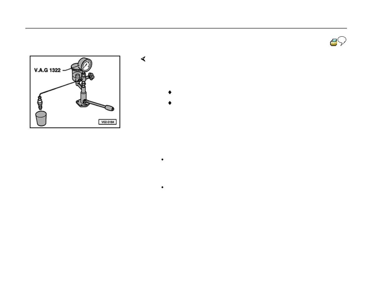
VAG1322 fuel injector test stand
Test conditions
Pressure gauge installed
Checking injector pressure
WARNING!
When testing fuel injectors, make sure that
the stream of fuel does not contact the hands
or any other bare skin. The fuel (expelled
under high pressure) can penetrate the skin,
and this could cause severe injuries or health

complications.
23-32
If injector opening pressure is not as specified:
Leak checking
- Connect fuel injector to injector test stand.
- Move pump lever down slowly to increase pressure.
- Read opening pressure when spray begins.
Specification (new): 190 to 200 bar (2750-2900 psi)
Wear limit: 170 bar (2465 psi)
- Replace that fuel injector.
Pressure gauge connected
- Move pump lever down slowly to maintain steady pressure of approx.
150 bar (2175 psi) for 10 seconds.
No fuel should leak from injector nozzle
- Replace any leaking injectors.
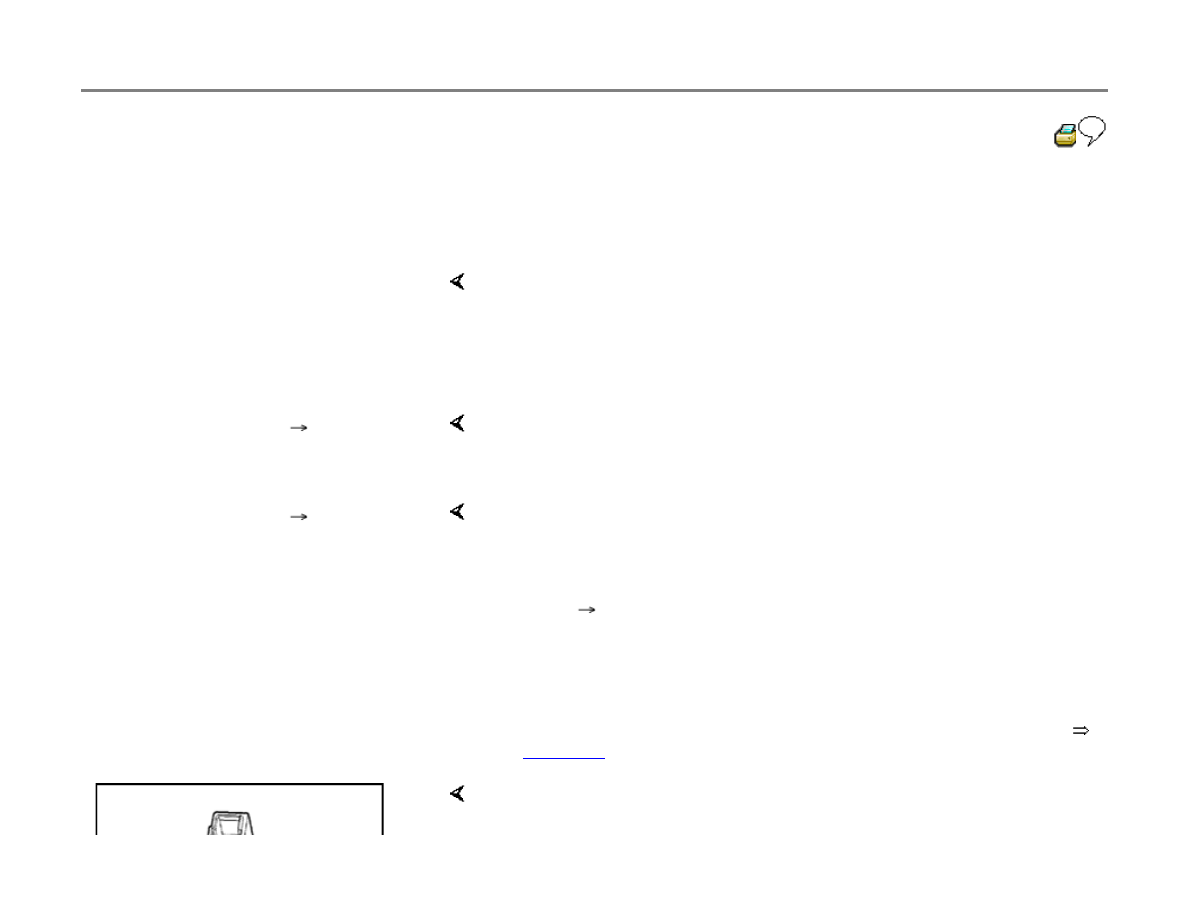
23-33
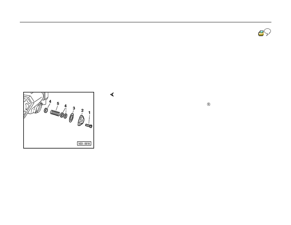
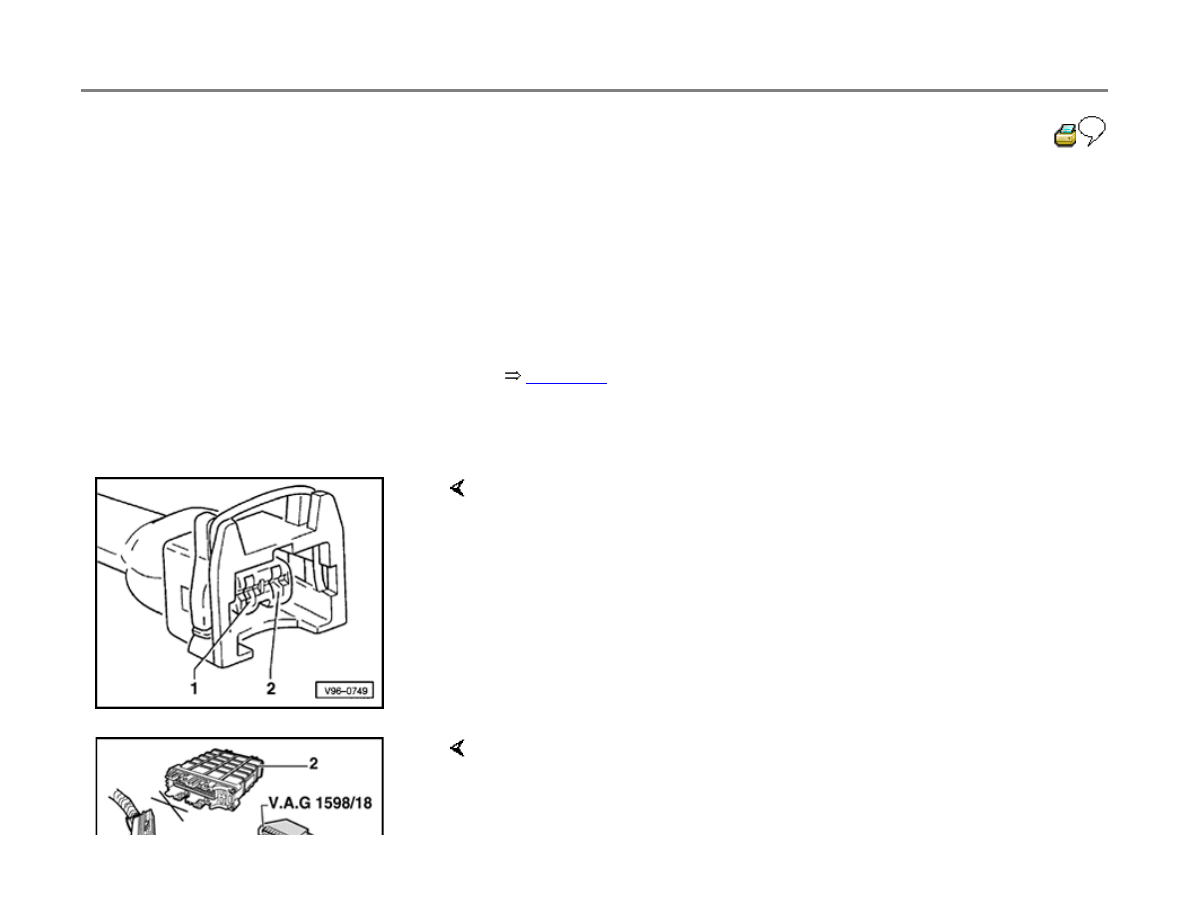
Timing control cover O-ring, replacing
WARNING!
Fire hazard! Do not have anything in the area
that can ignite Diesel fuel.
- Place clean cloth under Diesel injection pump.
- Remove cover screws -1-.
Use commercially available tool for Torx socket-head screws, e.g.
Hazet 2115-T30
- Remove cover -2- and carefully clean.
- Replace O-ring -3- and install cover using existing shims -4-.

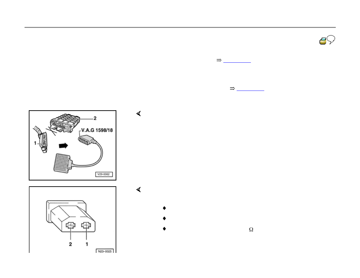
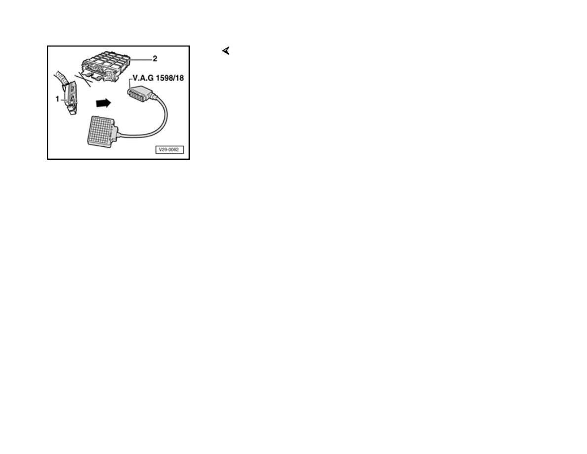
23-34
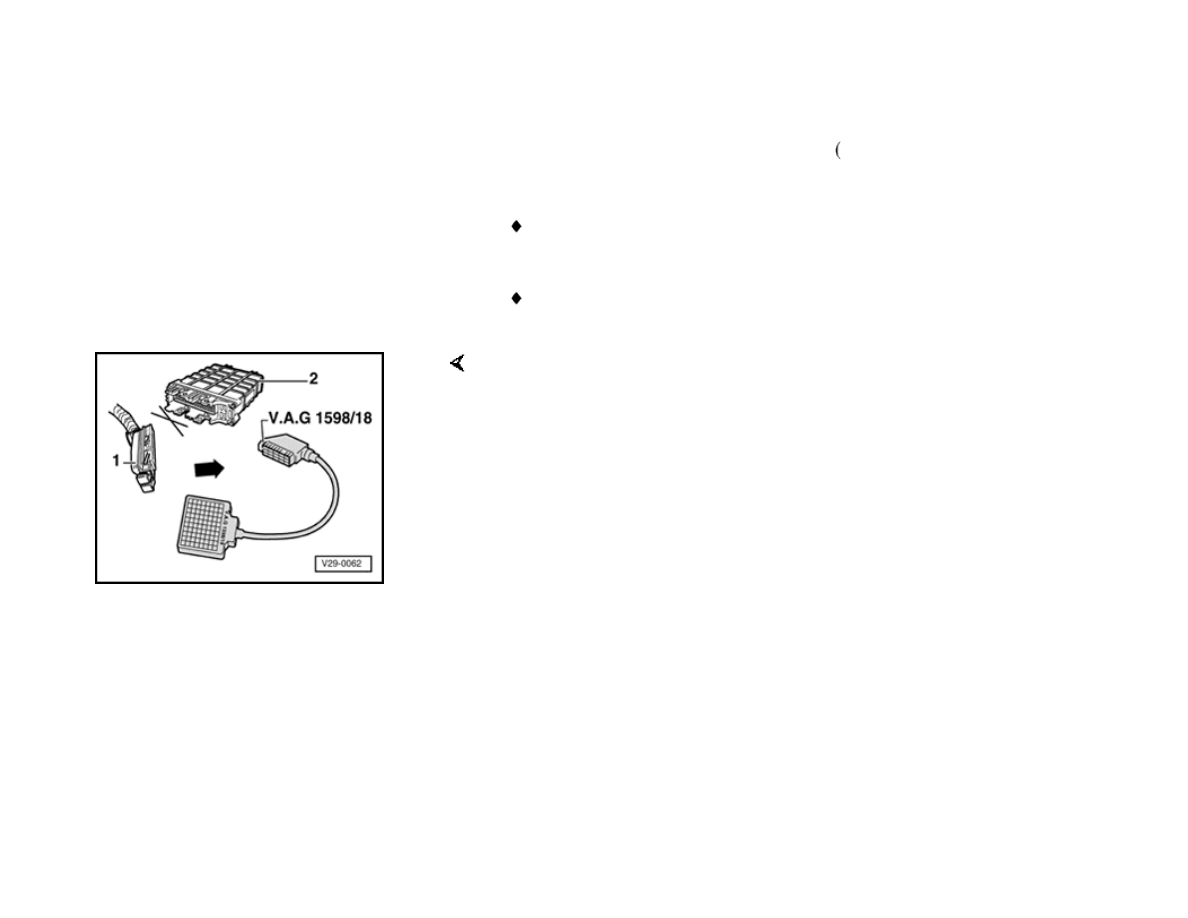
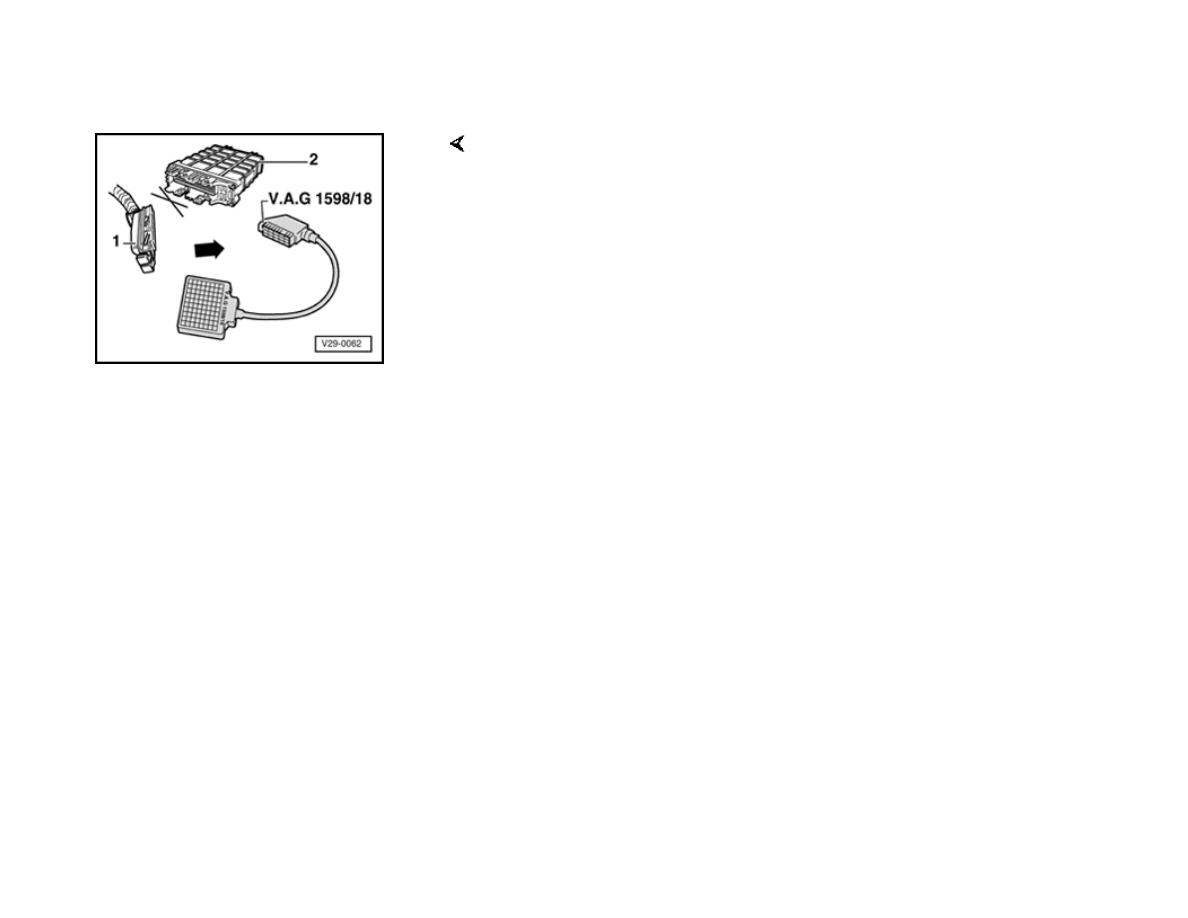
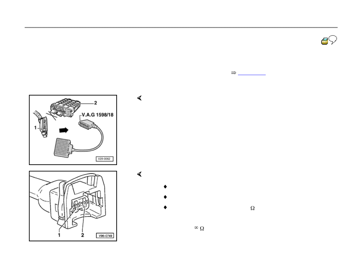
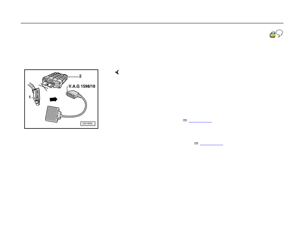
Wiring and component checks, using
VAG1598/18 test box
WARNING!
To guard against damage to electronic
components:
Be sure ignition is switched off, and the
correct measuring range is selected before
connecting test leads!
Always observe test conditions and
requirements!
Notes:
Use the Fluke 83 multimeter and VAG1527B
voltage tester, or equivalent, for the following
checks.
The specifications listed are valid for ambient
temperatures between 0 and +40 C (32
and 104 F).
If measurements deviate only slightly from
specified values, clean test equipment sockets
and connectors, then repeat the tests. Before
replacing any component, check wiring and
connections, particularly when a specified
resistance value is less than 10 ohms
W), and
repeat the measurement.
Make test box connections using adapters from
the VW1594 connector test kit.
Terminal numbers for vehicle connectors and
the test box sockets are identical.
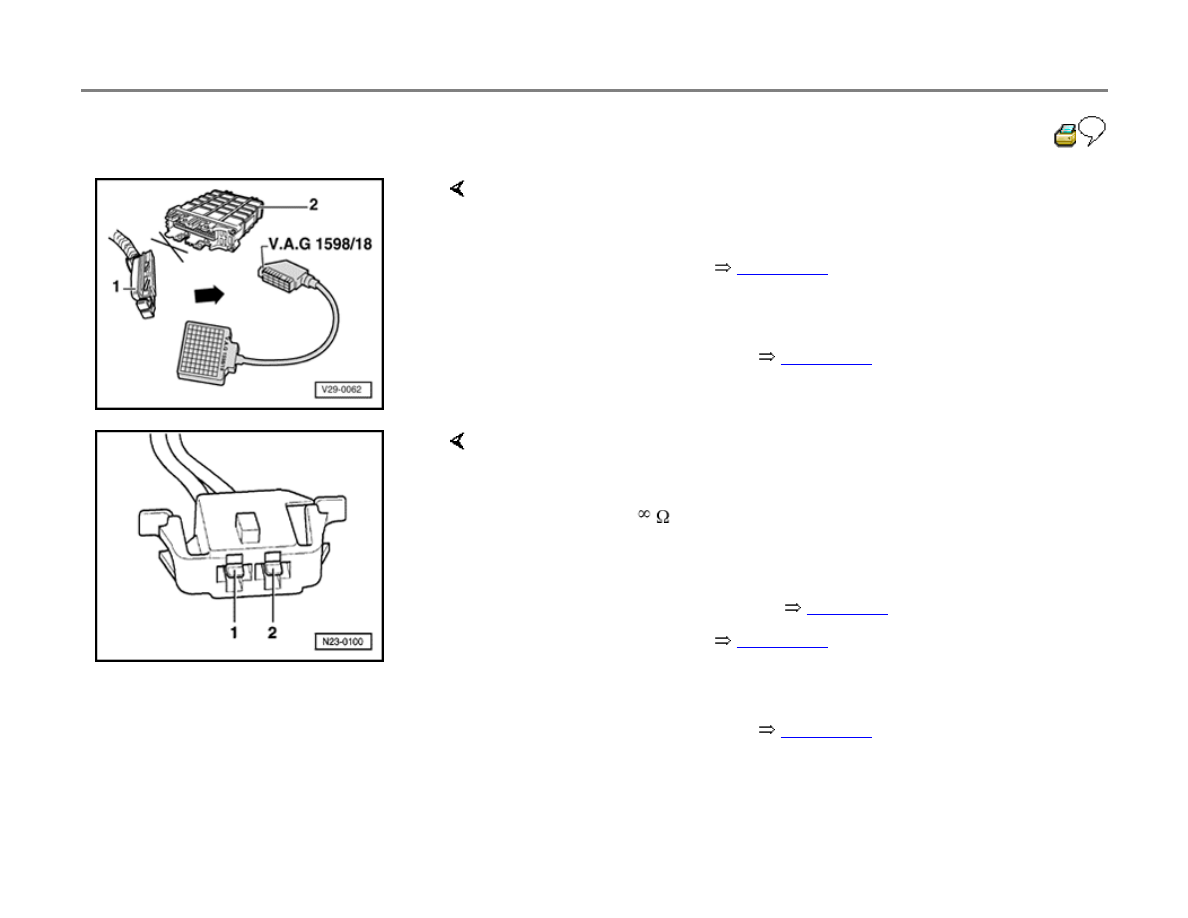
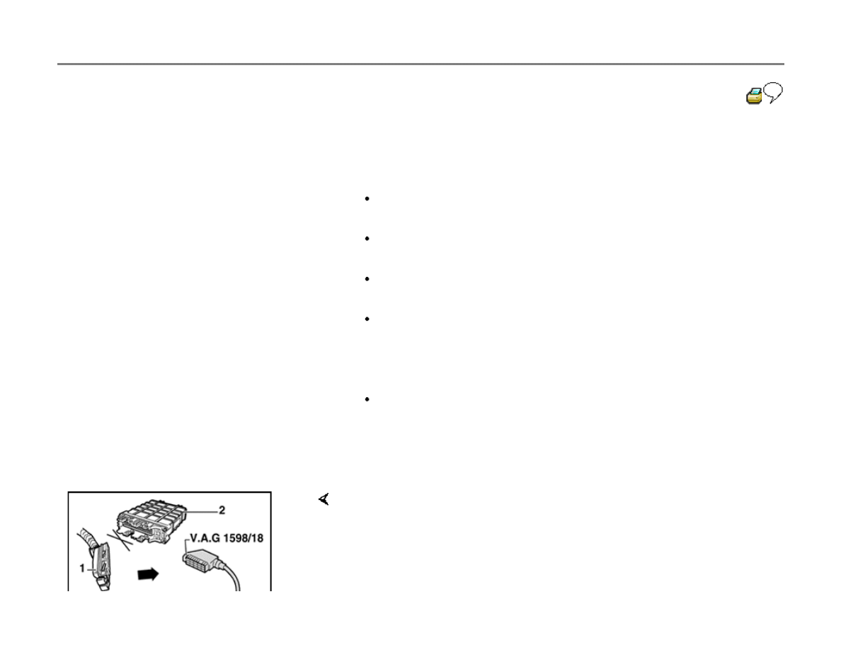
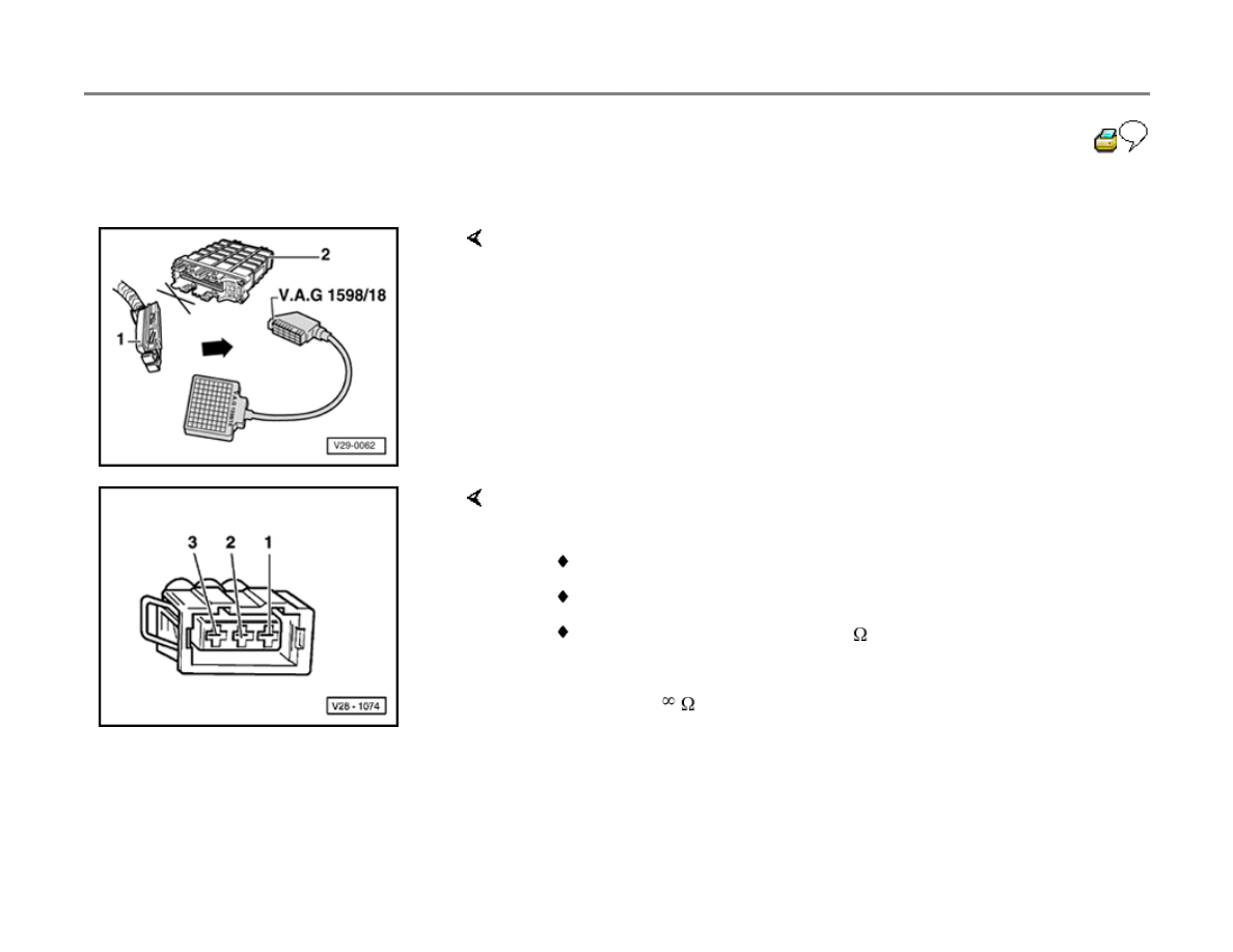
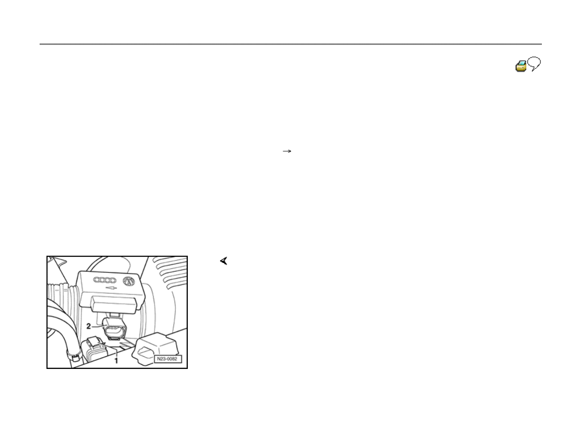
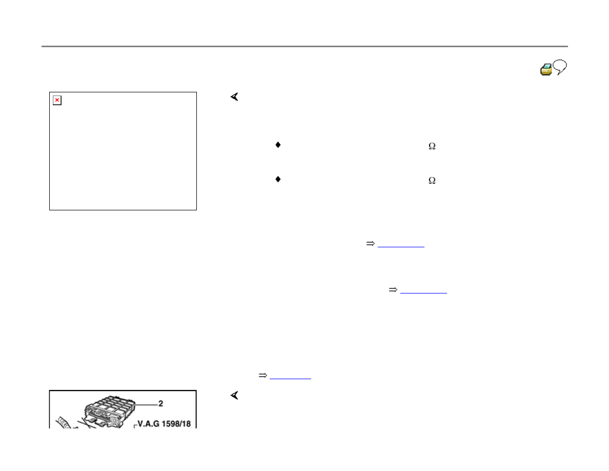
- With ignition off, disconnect harness connector -1- from Diesel DFI
ECM -2-, and connect test box to harness connector.
- Check as described by appropriate repair procedure.
23-35
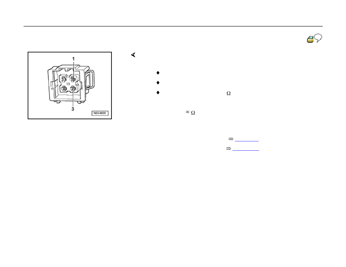
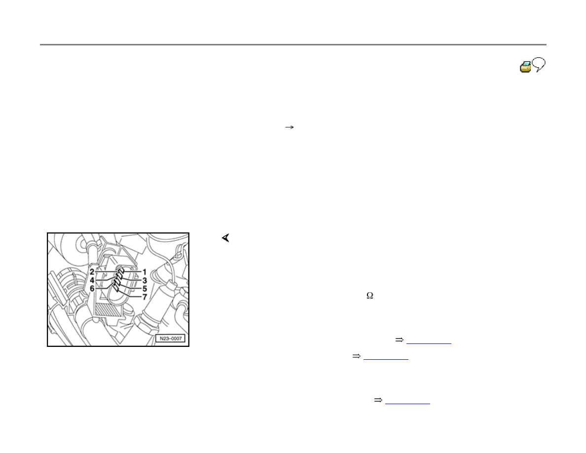
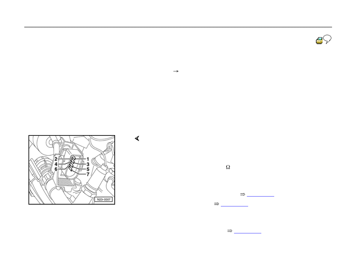
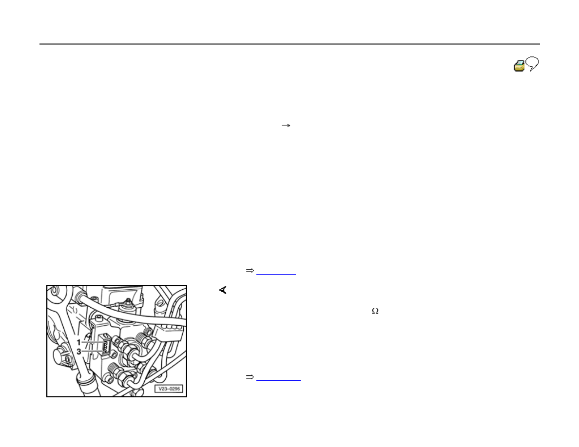
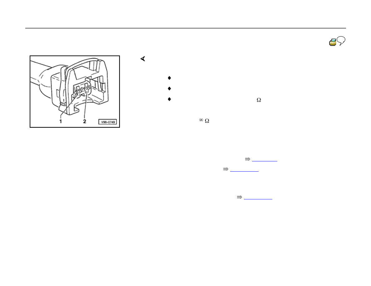
Engine speed (RPM) sensor, checking
The RPM sensor provides an engine speed
signal. If the sensor fails, the engine continues to
run using a back-up program. The signal from
needle lift sensor -G80- is used as a substitute.
Special tools, testers and auxiliary items
VAG1598/18 test box
Multimeter (Fluke 83 or equivalent)
VW1594 connector test kit
Electrical Wiring Diagrams, Troubleshooting
& Component Locations binder
Test sequence
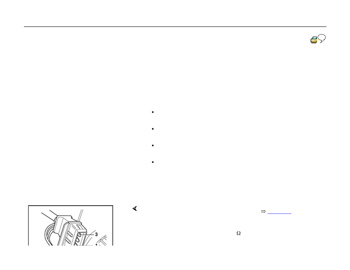
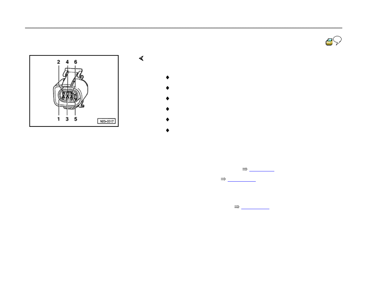
- Switch ignition off.
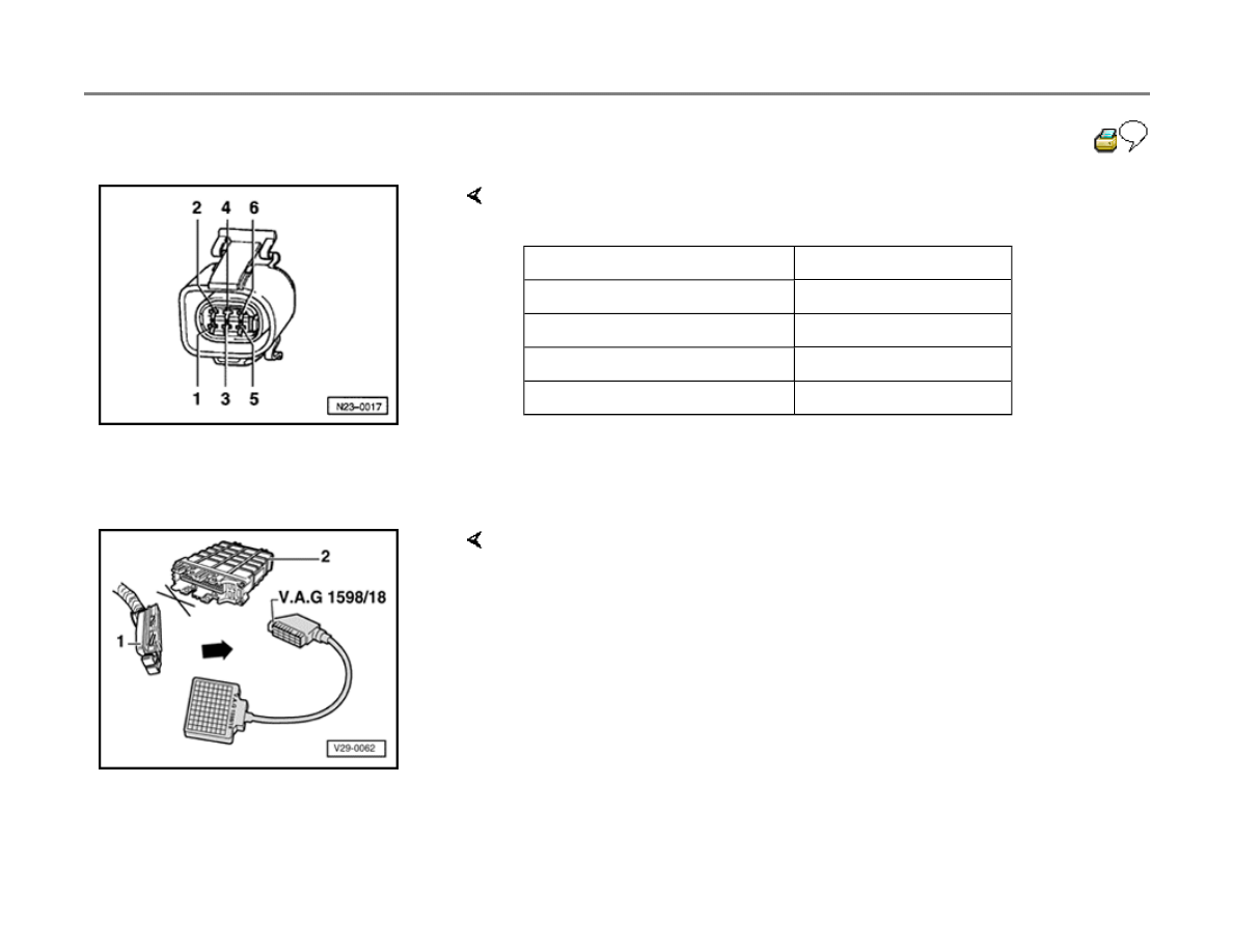
- Disconnect RPM sensor harness connector (
page 23-5
), connect
multimeter, and check resistance between harness connector terminals
1 and 2.
Specification: 1000 to 1500 ohms (
)

If resistance is not as specified:
Repair Manual, 1.9 Liter Turbo Diesel General, Engine (engine code
AHU), Repair Group 13.
- Replace engine speed sensor -G28-
- Display readiness code
page 01-43
.
23-36
If DTC memory was erased:
- Create readiness code again
page 01-47
.
If resistance is OK:
- Connect VAG1598/18 test box to Diesel DFI
ECM harness connector
page 23-34
.
If wiring is OK:
If DTC memory was erased:
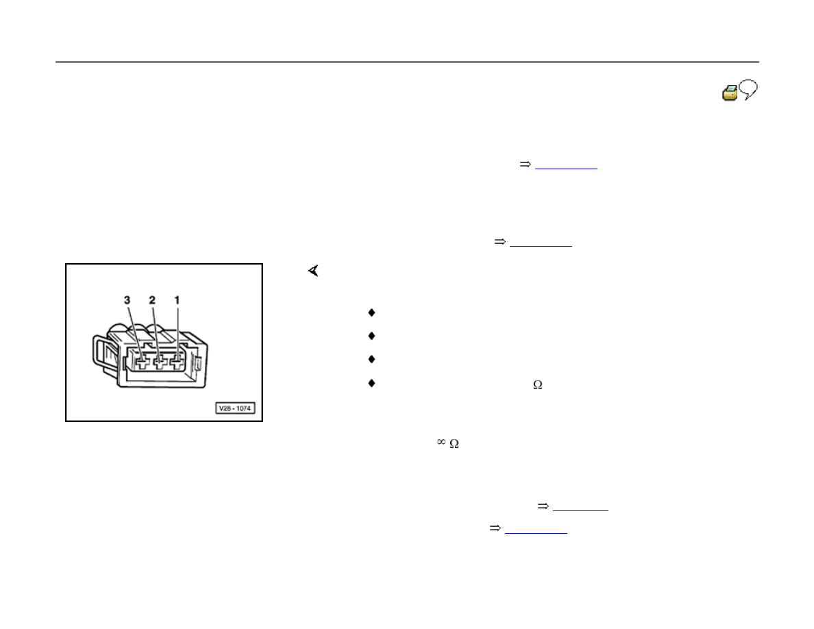
- Check wiring for open circuit between 3-pin connector and test box,
using wiring diagram:
Terminal 1 + test box socket 33
Terminal 2 + test box socket 8
Terminal 3 + test box socket 1
Wire resistance: 1.5 ohms (
) maximum
- Check wiring for short circuit between terminals at 3-pin connector,
using wiring diagram.
Specification:
(no continuity)
- Replace Diesel DFI ECM -J248-
page 23-5
, item 17 .
- Display readiness code
page 01-43
.

- Create readiness code again
page 01-47
.

23-37
Manifold Absolute Pressure (MAP) and
barometric pressure (BARO) sensors,
checking
Both pressure sensors are located inside the
Diesel Direct Fuel Injection (DFI) Engine Control
Module (ECM).
Special tools, testers and auxiliary items
VAG1551 or VAG1552 Scan Tool (ST)
VAG1551/3 adapter cable
VAG1397A turbocharger tester
Test sequence
- Connect VAG1551 or VAG1552 scan tool
page 01-9
.
- Switch ignition on (but do not start engine).
- Press buttons -0- and -1- to insert "Engine
Electronics" address word 01.
Rapid data transfer
HELP
Indicated on display

Select function XX
- Press buttons -0- and -8- to select "Read Measuring Value Block"
function 08, and press -Q- button to confirm input.
Read Measuring Value Block
HELP
Input display group number XXX
Indicated on display
- Press buttons -0-, -1- and -0- to select display group no. 10 (010).

23-38
- Press -Q- button to confirm input.
Read Measuring Value Block 10
0 mg/H 1027 mbar 1013 mbar 0.0 %
If pressures are not equal (as specified):
If value in display field 3 deviates:
If value in display field 3 still deviates:
- Compare values in display field 2 (BARO sensor -F96-) and display
field 3 (MAP sensor -G71-).
Specification: pressures equal ( 30 mbar)
- Compare scan tool values with pressure measured using VAG1397A
turbocharger tester.
Specification: pressures equal ( 30 mbar)
- Disconnect pressure hose from Diesel DFI ECM.
- Press
button.
- Press buttons -0- and -6- to select "End Output" function 06, and press
-Q- button to confirm input.
- Switch ignition off.
- Replace Diesel DFI ECM -J248-
page 23-5
, item 17 .
- Display readiness code
page 01-43
.

If DTC memory was erased:
- Create readiness code again
page 01-47
.

23-39
Engine Coolant Temperature (ECT)
sensor, checking
Special tools, testers and auxiliary items
VAG1551 or VAG1552 Scan Tool (ST)
VAG1551/3 adapter cable
VAG1598/18 test box
Multimeter (Fluke 83 or equivalent)
VW1594 connector test kit
Electrical Wiring Diagrams, Troubleshooting
& Component Locations binder
Test sequence
- Connect VAG1551 or VAG1552 scan tool.
page 01-9
.
- Start engine and let idle.

- Press buttons -0- and -1- to insert the "Engine
Electronics" address word 01.
Rapid data transfer
HELP
Select function XX
Indicated on display
- Press buttons -0- and -8- to select "Read Measuring Value Block"
function 08.
23-40
- Press -Q- button to confirm input.
Read Measuring Value Block
HELP
Input display group number XXX
Indicated on display
- Press buttons -0-, -0- and -7- to input display group no. 7 (007).
- Press -Q- button to confirm input.
Read Measuring Value Block 7
15.4
C
15.9
C 16.7
C
Note:
If the ECT sensor malfunctions, the fuel temperature sensor values are
substituted to provide a back-up.
If an unreasonable value appears in display field 4, or the fuel
temperature has been supplied as a substitute, check the ECT sensor
and wiring connections to the sensor as follows:
- Indicated on display
- Check ECT value in display field 4.
Value must increase uniformly and without interruption
- Press
button.
- Press buttons -0- and -6- to select "End Output" function 06.
- Press -Q- button to confirm input.
- Switch ignition off.

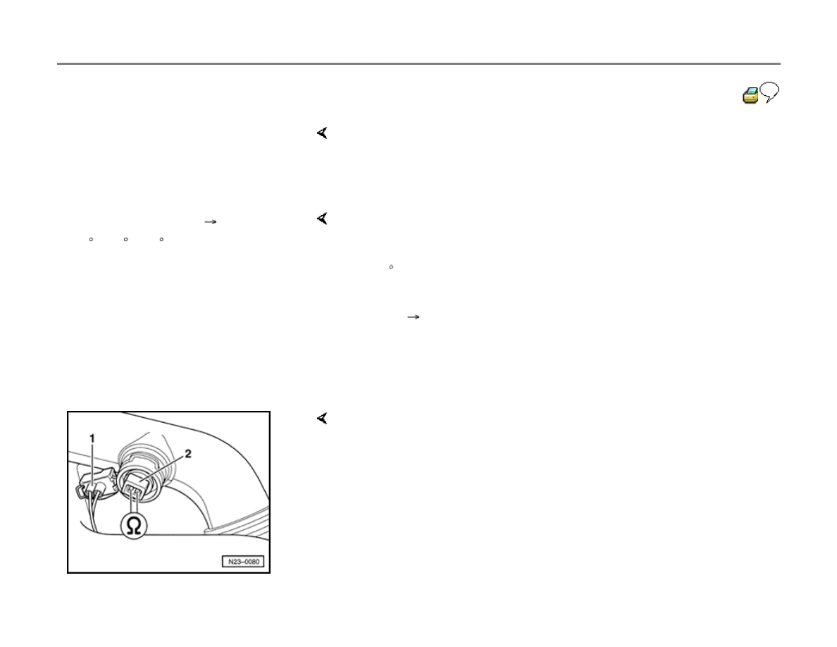
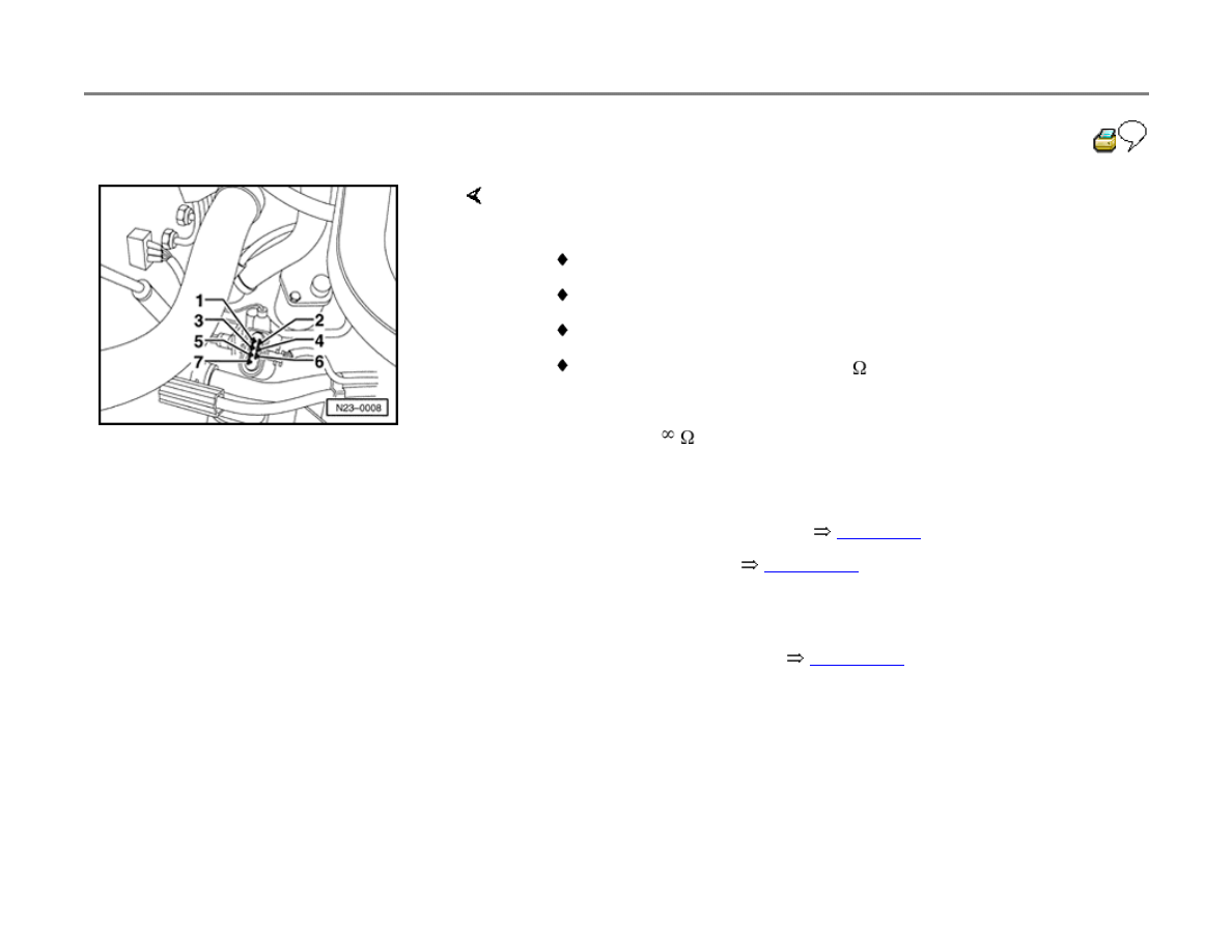
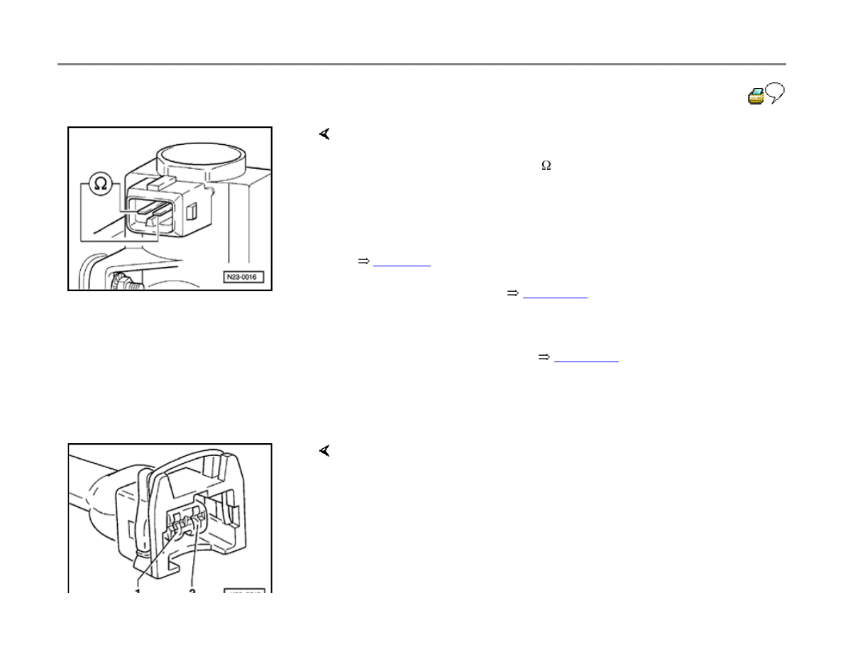
- Disconnect harness connector from ECT sensor -1-.
23-41
- Measure resistance between sensor terminals 1
and 3.
If resistance is outside the specified range:
If DTC memory was erased:
If resistance is OK:
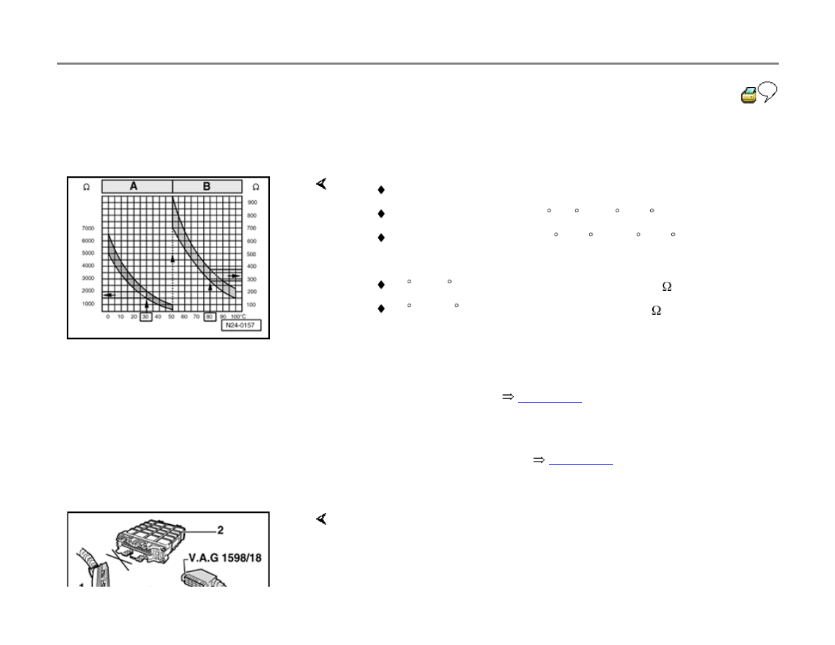
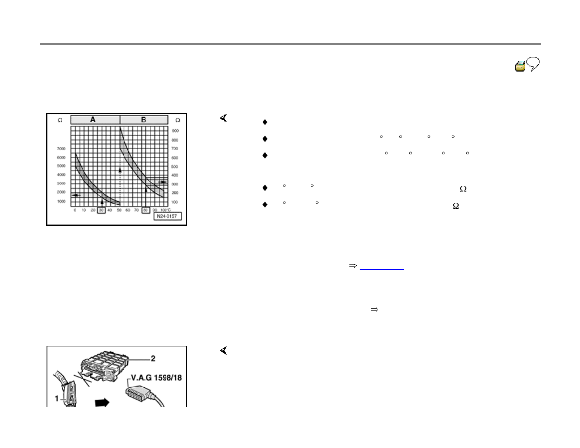
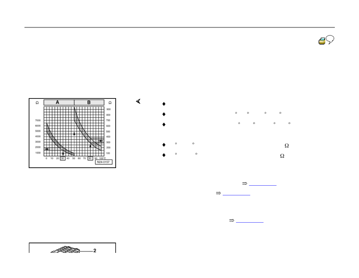
Specifications: refer to diagram for resistance values
Scale A: for temperatures 0 -50 C (32 -122 F)
Scale B: for temperatures 50 -100 C (122 -212 F)
Examples:
30 C (86 F) corresponds to 1500-2000 ohms (
) resistance
80 C (176 F) corresponds to 275-375ohms (
) resistance
- Replace engine coolant temperature sensor -G62-.
- Display readiness code
page 01-43
.
- Create readiness code again
page 01-47
.
- Connect VAG1598/18 test box to Diesel DFI ECM connector.
23-42
If wiring is OK:
Note:
Disconnecting the engine coolant temperature sensor always generates a
DTC, which must be erased.
- Check wiring for open circuit between 4-pin connector and test box,
using wiring diagram.
Terminal 1 + test box socket 33
Terminal 3 + test box socket 14
Wire resistance: 1.5 ohms (
) maximum
- Check wiring for short circuit between terminals at 4-pin connector.
Specification:
(no continuity)
- Replace Diesel DFI ECM -J248-
page 23-5
, item 17 .
- Check and erase DTC memory
page 01-41
.
23-43
Brake light switch and brake vacuum
vent valve switch, checking
Because the Diesel injection system uses a
throttle position sensor that could malfunction, for
reasons of safety, the engine is regulated when
the brakes are applied. The Diesel Direct Fuel
Injection (DFI) Engine Control Module (ECM)
requires signals from the brake light switch and
the brake vacuum vent valve switch for this
function.
If the brakes are operated while the accelerator
pedal remains in a constant position, engine
speed is immediately reduced to idle. Incorrectly
adjusted switches could lead to unnecessary
control.
Special tools, testers and auxiliary items
VAG1551 or VAG1552 Scan Tool (ST)
VAG1551/3 adapter cable
VAG1598/18 test box
Multimeter (Fluke 83 or equivalent)

VW1594 connector test kit
Electrical Wiring Diagrams, Troubleshooting
& Component Locations binder
Test sequence
- Connect VAG1551 or VAG1552 scan tool
page 01-9
.
23-44
- Switch ignition on.
- Press buttons -0- and -1- to insert the "Engine
Electronics" address word 01.
Rapid data transfer
HELP
Select function XX
Indicated on display
- Press buttons -0- and -8- to select "Read Measuring Value Block"
function 08.
- Press -Q- button to confirm input.
Read Measuring Value Block
HELP
Input display group number XXX
Indicated on display
- Press buttons -0-, -0- and -6- to input display group no. 6 (006).
- Press -Q- button to confirm input.
- Check value in display field 2.
Read Measuring Value Block 6
0 km/h 0 0 0 000000 255
Specified display: 0 0 0
Center display element = Brake vacuum vent valve switch
Right display element = Brake light switch
- Press brake pedal slowly.
Read Measuring Value Block 6
0 km/h 0 1 1 000000 255
Specified display: 0 1 1

Note:
Both display elements must change from "0" to "1" at the same time.
23-45
- Release brake pedal slowly into rest position
again
Read Measuring Value Block 6
0 km/h 0 0 0 000000 255
If one or both elements do not change:
If center display element does not change:
Both display elements must change from "1" to "0" again.
- Adjust brake vacuum vent valve switch activation point by turning
switch.
- Adjust brake light switch activation point by moving plunger.
- Press
button.
- Press buttons -0- and -6- to select "End Output" function 06, and press
-Q- button to confirm input.
- Switch ignition off.
- Disconnect harness connector from brake vacuum vent valve switch -
1-.
- Measure resistance across switch terminals.
Specifications:
Brake pedal not depressed: less than 10 ohms (
)
Brake pedal depressed:
(no continuity)

If resistance is not as specified:
- Replace brake vacuum vent valve switch -F47-.
23-46
- Display readiness code
page 01-43
.
If DTC memory was erased:
- Create readiness code again
page 01-47
.
If resistance values are OK:
- Connect VAG1598/18 test box to Diesel DFI ECM connector.
- Check wiring for open circuit between test box and harness connector,
using wiring diagrams:
Terminal 1 and test box socket 20
Terminal 2 and test box socket 33
Wire resistance: max. 1.5 ohms (
)
- Check wiring for short circuit between connector terminals.

If the right display element in display field 2 (brake light switch) does not
change:
Specification:
(no continuity)
- Press
button.
23-47
- Press buttons -0- and -6- to select "End Output"
function 06, and press -Q- button to confirm
input.
- Switch ignition off.
- Switch multimeter to 20 volt range.
- Connect multimeter using adapters from
VW1594 connector test kit, and check voltage
between test box sockets 1 and 44.
Specifications:
Brake pedal not depressed: 0 (no voltage)
Brake pedal depressed: approx. battery
voltage (B+)
If there is no voltage:
- Check brake lights.
If the brake lights are OK:
-
Check wiring to brake light switch for open or

short circuit, using wiring diagrams.
If the brake lights do not come on:
- Replace brake light switch -F-.
- Display readiness code
page 01-43
.
If DTC memory was erased:
- Create readiness code again
page 01-47
.
23-48
Clutch vacuum vent valve switch,
checking
The clutch vacuum vent valve switch -F36- signal
provides the Diesel Direct Fuel Injection (DFI)
Engine Control Module (ECM) with information
about clutch engagement. This signal is used to
provide smoother disengaging and engaging,
and to prevent the engine racing when cruise
control is in use.
Special tools, testers and auxiliary items
VAG1551 or VAG1552 Scan Tool (ST)
VAG1551/3 adapter cable
VAG1598/18 test box
Multimeter (Fluke 83 or equivalent)
VW1594 connector test kit
Electrical Wiring Diagrams, Troubleshooting
& Component Locations binder
Test sequence

- Connect VAG1551 or VAG1552 scan tool
page 01-9
.
- Switch ignition on.
- Press buttons -0- and -1- to insert the "Engine
Electronics" address word 01.
Rapid data transfer
HELP
Select function XX
Indicated on display
23-49
- Press buttons -0- and -8- to select "Read
Measuring Value Block" function 08, and press -
Q- button to confirm input.
Read Measuring Value Block
HELP
Input display group number XXX
Indicated on display
- Press buttons -0-, -0- and -6- to input display group no. 6 (006), and
press -Q- button to confirm input.
- Check value in display field 2.
Read Measuring Value Block 6
0 km/h 0 0 0 000000 255
Specification: 0 0 0
- Depress clutch pedal.
Read Measuring Value Block 6
0 km/h 1 0 0 000000 255
If left display element does not change:
Specification: 1 0 0 (left display element must change to 1)
- Press
button.
- Press buttons -0- and -6- to select "End Output" function 06, and press
-Q- button to confirm input.
- Switch ignition off.
- Disconnect harness connector from clutch vacuum vent valve switch
page 23-4
.
- Measure resistance across switch terminals. Specifications:

Clutch pedal not depressed: max. 10 ohms (
)
Clutch pedal depressed:
(no continuity)
23-50
If resistance is not as specified:
If DTC memory was erased:
If resistance values are OK:
- Replace clutch vacuum vent valve switch -F36-.
- Display readiness code
page 01-43
.
- Create readiness code again
page 01-47
.
If wiring is OK:
If DTC memory was erased:
- Connect VAG1598/18 test box to Diesel DFI ECM connector.
- Check wiring for short circuit between connector terminals.
Specification:
(no continuity)
- Replace Diesel DFI ECM -J248-
page 23-5
, item 17 .
- Display readiness code
page 01-43
.
- Create readiness code again
page 01-47
.

23-51
Intake Air Temperature (IAT) sensor,
checking
Special tools, testers and auxiliary items
VAG1551 or VAG1552 Scan Tool (ST)
VAG1551/3 adapter cable
VAG1598/18 test box
Multimeter (Fluke 83 or equivalent)
VW1594 connector test kit
Electrical Wiring Diagrams, Troubleshooting
& Component Locations
Test sequence
- Connect VAG1551 or VAG1552 scan tool
page 01-9
.
- Start engine and let idle.

- Press buttons -0- and -1- to insert the "Engine
Electronics" address word 01.
Rapid data transfer
HELP
Select function XX
Indicated on display
- Press buttons -0- and -8- to select "Read Measuring Value Block"
function 08.
- Press -Q- button to confirm input.
23-52
Read Measuring Value Block
HELP
Input display group number XXX
Indicated on display
- Press buttons -0-, -0- and -7- to input display group no. 7 (007).
- Press -Q- button to confirm input.
Read Measuring Value Block 7
15.4
C 15.9
C 16.7
C
If an implausible value appears in display field 3, or a substitute value of
136.8 C is displayed, check intake air temperature sensor and sensor
wiring:
- Indicated on display
- Press
button.
- Press buttons -0- and -6- to select "End Output" function 06.
- Press -Q- button to confirm input.
- Switch ignition off.
- Disconnect harness connector -1- from intake air temperature sensor -
2-.
23-53
- Measure resistance across sensor terminals.
If resistance is outside the specified range:
If DTC memory was erased:
If resistance is OK:
Specifications: refer to diagram for resistance values
Scale A: for temperatures 0 -50 C (32 -122 F)
Scale B: for temperatures 50 -100 C (122 -212 F)
Examples:
30 C (86 F) corresponds to 1500-2000 ohms (
) resistance
80 C (176 F) corresponds to 275-375ohms (
) resistance
- Replace Intake Air Temperature (IAT) sensor -G72-.
- Display readiness code
page 01-43
.
- Create readiness code again
page 01-47
.
- Connect VAG1598/18 test box to Diesel DFI ECM connector.

23-54
If wiring is OK:
If DTC memory was erased:
- Check wiring for open circuit between test box and harness connector,
using wiring diagrams:
Terminal 1 and test box socket 64
Terminal 2 and test box socket 33
Wire resistance: max. 1.5 ohms (
)
- Check wiring for short circuit between connector terminals.
Specification:
(no continuity)
- Replace Diesel DFI ECM -J248-
page 23-5
, item 17 .
- Display readiness code
page 01-43
.
- Create readiness code again
page 01-47
.
23-55
TDI system current supply, checking
Special tools, testers and auxiliary items
VAG1598/18 test box
Multimeter (Fluke 83 or equivalent)
VW1594 connector test kit
Electrical Wiring Diagrams, Troubleshooting
& Component Locations binder
Test requirements
Battery voltage OK
Checking
- Switch ignition off.
- Connect VAG1598/18 test box to Diesel DFI ECM connector.
- Bridge sockets 42 and 46 using adapters from VW1594 connector test
kit.
23-56
- Measure voltage between test box sockets:
45 and 1
68 and 1
23 and 1
23 and 24
Specification: approx. battery voltage (B+)
If voltage is not OK:
- Check power supply (terminal 30. B+) relay -
J317- at terminal 30.
- Check wiring connections for open circuit, short
circuit and contact resistance at terminals, using
wiring diagrams.
If the wiring and the relay are OK:
- Replace Diesel DFI ECM -J248-
page 23-5
,
item 17 .

- Display readiness code
page 01-43
.
If DTC memory was erased:
- Create readiness code again
page 01-47
.

23-57
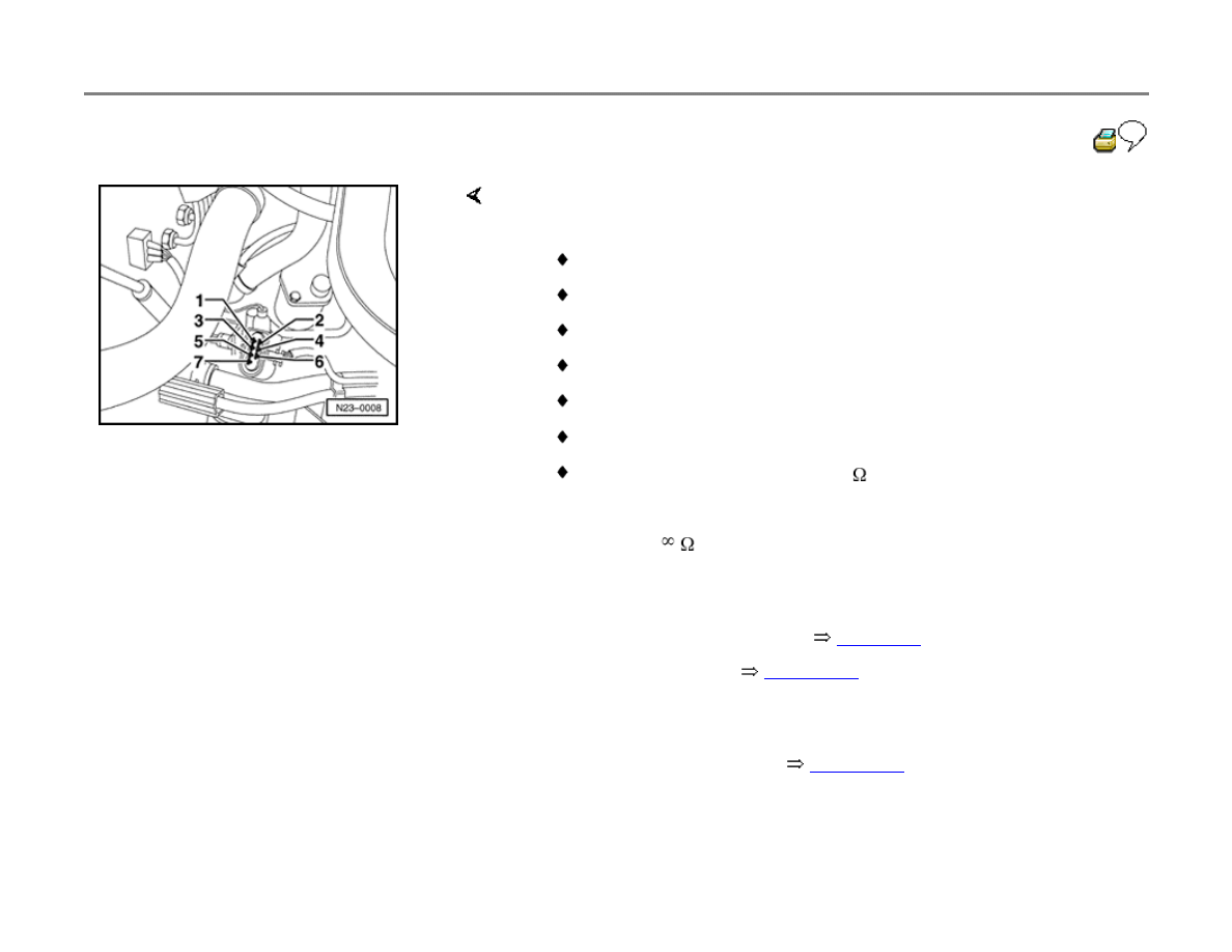
Fuel temperature sensor, checking
Special tools, testers and auxiliary items
VAG1551 or VAG1552 Scan Tool (ST)
VAG1551/3 adapter cable
VAG1598/18 test box
Multimeter (Fluke 83 or equivalent)
VW1594 connector test kit
Electrical Wiring Diagrams, Troubleshooting
& Component Locations binder
Test sequence
- Connect VAG1551 or VAG1552 scan tool.
page 01-9
- Start engine and let idle.

- Press buttons -0- and -1- to insert the "Engine
Electronics" address word 01.
Rapid data transfer
HELP
Select function XX
Indicated on display
- Press buttons -0- and -8- to select "Read Measuring Value Block"
function 08.
- Press -Q- button to confirm input.
23-58
Read Measuring Value Block
HELP
Input display group number XXX
Indicated on display
- Press buttons -0-, -0- and -7- to input display group no. 7 (007).
- Press -Q- button to confirm input.
Read Measuring Value Block 7
15.4
C 15.9 5C 16.7
C
If an implausible value appears in display field 1, or a substitute value of -
5.4 C is displayed, check fuel temperature sensor and sensor and
wiring:
- Indicated on display
- Press
button.
- Press buttons -0- and -6- to select "End Output" function 06.
- Press -Q- button to confirm input.
- Switch ignition off.
- Disconnect fuel temperature sensor harness connector (connection to
Diesel injection pump metering control).
23-59
- Measure sensor resistance at terminals 4 and
7
- Measure resistance across sensor terminals 4
and 7.
If resistance is outside the specified range:
If DTC memory was erased:
If resistance is OK:
Specifications: refer to diagram
Scale A: for temperatures 0 -50 C (32 -122 F)
Scale B: for temperatures 50 -100 C (122 -212 F)
Examples:
30 C (86 F) corresponds to 1500-2000 ohms (
) resistance
80 C (176 F) corresponds to 275-375ohms (
) resistance
- Replace diesel fuel injection pump
page 23-18
.
- Display readiness code
page 01-43
.
- Create readiness code again
page 01-47
.

- Connect VAG1598/18 test box to Diesel DFI ECM connector.

23-60
If wiring is OK:
If DTC memory was erased:
- Check wiring for open circuit between test box and harness connector,
using wiring diagrams:
Terminal 7 and test box socket 63
Terminal 4 and test box socket 33
Wire resistance: max. 1.5 ohms (
)
- Check wiring for short circuit between connector terminals.
Specification:
(no continuity)
- Replace Diesel DFI ECM -J248-
page 23-5
, item 17 .
- Display readiness code
page 01-43
.
- Create readiness code again
page 01-47
.
23-61
Modulating piston displacement sensor
and quantity adjuster, checking
The quantity adjuster -N146- is an electro-
magnetic positioner, controlled by the Diesel
Direct Fuel Injection (DFI) ECM via duty cycle
(on-off ratio). The eccentric shaft on the quantity
adjuster moves the modulating piston (on the
high-pressure piston), regulating the amount of
fuel injected.
The modulating piston displacement sensor
provides the ECM with information on quantity
adjuster position, and the ECM then calculates
the required amount of fuel for injection.
Special tools, testers and auxiliary items
VAG1551 or VAG1552 Scan Tool (ST)
VAG1551/3 adapter cable
VAG1598/18 test box
Multimeter (Fluke 83 or equivalent)
VW1594 connector test kit

Electrical Wiring Diagrams, Troubleshooting
& Component Locations binder
Checking
- Connect VAG1551 or VAG1552 scan tool
page 01-9
.
- Start engine and let idle
23-62
- Press buttons -0- and -1- to insert the "Engine
Electronics" address word 01.
Rapid data transfer
HELP
Select function XX
Indicated on display
- Press buttons -0- and -8- to select "Read Measuring Value Block"
function 08, and press -Q- button to confirm input.
Read Measuring Value Block
HELP
Input display group number XXX
Indicated on display
- Press buttons -0-, -0- and -1- to input display group no. 1 (001), and
press -Q- button to confirm input.
Read Measuring Value Block 1
840 rpm 6.5 mg/H 1.480 V 87.3
C
Indicated on display
Note:
Continue only when temperature display is as specified.
- Check engine coolant temperature value in display field 4.
Specification: at least 85 C
Read Measuring Value Block 1
840 rpm 6.5 mg/H 1.480 V 87.3 5C
If voltage is not as specified:
- Check voltage supply value in display field 3 (for modulating piston
displacement sensor).
Specification: 1.250 to 1.750 volts

- Check modulating piston displacement sensor
page 23-63
.
- Check quantity adjuster
page 23-65
.
23-63
Modulating piston displacement sensor,
checking
- Press
button.
- Press buttons -0- and -6- to select "End Output"
function 06.
- Press -Q- button to confirm input.
- Switch ignition off.
If resistance is not as specified:
If DTC memory was erased:
- Disconnect fuel temperature sensor harness connector (connection to
fuel pump quantity adjuster).
- Measure resistance across connector terminals 1 and 2, and terminals
2 and 3.
Specification: 5 to 7 ohms ( )
- Replace diesel fuel injection pump
page 23-18
.
- Display readiness code
page 01-43
.
- Create readiness code again
page 01-47
.
If resistance is OK:
- Connect VAG1598/18 test box to Diesel DFI ECM connector.
23-64
If wiring is OK:
If DTC memory was erased:
- Check wiring for open circuit between test box and harness connector,
using wiring diagrams:
Terminal 1 and test box socket 29
Terminal 2 and test box socket 7
Terminal 3 and test box socket 52
Wire resistance: max. 1.5 ohms (
)
- Check wiring for short circuit between connector terminals.
Specification:
(no continuity)
- Replace Diesel DFI ECM -J248-
page 23-5
, item 17 .
- Display readiness code
page 01-43
.
- Create readiness code again
page 01-47
.
23-65
Quantity adjuster, checking
- Press
button.
- Press buttons -0- and -6- to select "End Output"
function 06.
- Press -Q- button to confirm input.
- Switch ignition off.
If resistance is not as specified:
If DTC memory was erased:
If resistance is OK:
- Disconnect quantity adjuster harness connector (connector to Diesel
injection pump quantity adjuster).
- Measure resistance between connector terminals 5 and 6.
Specification: 0.5-2.5 ohms ( )
- Replace diesel fuel injection pump
page 23-18
.
- Display readiness code
page 01-43
.
- Create readiness code again
page 01-47
.
- Connect VAG1598/18 test box to Diesel DFI ECM connector.
23-66
If wiring is OK:
If DTC memory was erased:
- Check wiring for open circuit between test box and harness connector,
using wiring diagrams:
Terminal 5 and test box socket 23
Terminal 5 and test box socket 45
Terminal 5 and test box socket 68
Terminal 6 and test box socket 4
Terminal 6 and test box socket 5
Terminal 6 and test box socket 49
Wire resistance: max. 1.5 ohms (
)
- Check wiring for short circuit between connector terminals.
Specification:
(no continuity)
- Replace Diesel DFI ECM -J248-
page 23-5
, item 17 .
- Display readiness code
page 01-43
.
- Create readiness code again
page 01-47
.
23-67
Needle lift sensor, checking
The needle lift sensor signal determines the start
of injection during normal operation by closed-
loop control based on RPM, load and
temperature. If the sensor malfunctions, control
switches to open-loop, based on RPM and load.
Special tools, testers and auxiliary items
VAG1598/18 test box
Multimeter (Fluke 83 or equivalent)
VW1594 connector test kit
Electrical Wiring Diagrams, Troubleshooting
& Component Locations binder
Test sequence
- Switch ignition off.
- Disconnect harness connector -1- for needle lift sensor.
- Measure resistance across connector terminals.
Specification: 80 to 120 ohms ( )

If resistance is not as specified:
- Replace cyl. 3 injector
page 23-9
, item 14 .
- Display readiness code
page 01-43
.
23-68
If DTC memory was erased:
- Create readiness code again
page 01-47
.
If resistance is OK:
- Connect VAG1598/18 test box to Diesel DFI ECM connector.
If wiring is OK:
- Check for open circuit between test box and connector:
Terminal 1 and test box socket 12
Terminal 2 and test box socket 11
Wire resistance: max. 1.5 ohms (
)
- Check wiring for short circuit between connector terminals.
Specification:
(no continuity)

- Replace Diesel DFI ECM -J248-
page 23-5
, item 17 , and display
readiness code
page 01-43
.
- If DTC memory was erased, create readiness code again
page 01-
47
.
23-69
Quantity adjuster control range,
checking
The control range of the fuel injection quantity
adjuster can be checked using output Diagnostic
Test Mode (DTM) function 03, and "Read
Measuring Value Block" function 08. In the output
DTM, activate cold start injector -N108-, then exit
using the -C- button. With this sequence, the cold
start injector continues to be pulsed, and the
quantity adjuster control range can be displayed
using "Read Measuring Value Block" display
group 4.
Special tools, testers and auxiliary items
VAG1551 or VAG1552 Scan Tool (ST)
VAG1551/3 adapter cable
VAG1598/18 test box
Multimeter (Fluke 83 or equivalent)
VW1594 connector test kit
Electrical Wiring Diagrams, Troubleshooting

& Component Locations binder

23-70
Checking
- Connect VAG1551 or VAG1552 scan tool
page 01-9
.
- Start engine and let idle.
- Press buttons -0- and -1- to insert the "Engine
Electronics" address word 01.
Rapid data transfer
HELP
Select function XX
Indicated on display
- Press buttons -0- and -3- to select "Output Diagnostic Test Mode"
function 03, and press -Q- button to confirm input.
Rapid data transfer
Q
03 - Output Diagnostic Test Mode
Indicated on display
Note:
Individual DTM components are activated for 30seconds. Various work
sequences must be carried out with the scan tool within this period as well
as reading the displayed values. Read over the following work sequence
first to familiarize yourself with the procedure.
- Press -Q- button to confirm input.
Output Diagnostic Test Mode
Cold Start Injector-N108
Indicated on display

- Press -C- button.
- Press buttons -0- and -8- to select "Read Measuring Value Block"
function 08.
- Press -Q- button to confirm input.
23-71
Read Measuring Value Block
HELP
Input display group number XXX
Indicated on display
- Press buttons -0-, -0- and -4- to input display group no. 4 (004).
- Press -Q- button to confirm input.
Read Measuring Value Block 4
840 rpm 0.9
BTDC 0.9
BTDC 3 %
Indicated on display
Note:
The displays in display fields 3 and 4 must fluctuate within following
control range:
Note:
Due to the slow refresh rate of the VAG1551 scan tool, the displayed
values can greatly vary. Ensure that the lowest value only in display field
3 lies between 1.0 and 4.0 and the highest value lies between 14.0 and
17.4. Ensure that the lowest value in display field 4 lies between 2 and 5,
and the highest value between 90 and 95.
Specification display field 3:
Lower range: 1 ATDC to 4.0 BTDC
Upper range: 14.0 to 17.4 BTDC
Specification display field 4:
Lower range: 2 to 5%
Upper range: 90 to 95%
23-72
If the values are not as specified, check the cold
start injector as follows:
- Press
button.
- Press buttons -0- and -6- to select "End Output"
function 06.
- Press -Q- button to confirm input.
- Switch ignition off.
- Disconnect Diesel injection pump harness
connector.
page 23-4
If resistance is not as specified:
page 23-10
- Measure resistance between connector terminals 2 and 3.
Specification: 12 to 20 ohms ( )
- Replace cold start injector -N108-.

If DTC memory was erased:
- Display readiness code
page 01-43
.
- Create readiness code again
page 01-47
.
23-73
If resistance is OK:
- Connect VAG1598/18 test box to Diesel DFI ECM connector.
- Check wiring for open circuit between test box and 3-pin harness
connector, using wiring diagrams:
Terminal 2 and test box socket 51
Terminal 3 and test box socket 68
Wire resistance: max. 1.5 ohms (
)
- Check wiring for short circuit between connector terminals.
Specification:
(no continuity)
23-74
If wiring is OK:
- Replace Diesel DFI ECM -J248-
page 23-5
,
item 17 .
- Display readiness code
page 01-43
.
If DTC memory was erased:
- Create readiness code again
page 01-47
.

23-75
Boost pressure control, checking
Special tools, testers and auxiliary items
VAG1551 or VAG1552 Scan Tool (ST)
VAG1551/3 adapter cable
VAG1397A turbocharger tester
VAG1598/18 test box
Multimeter (Fluke 83 or equivalent)
VW1594 connector test kit
Electrical Wiring Diagrams, Troubleshooting
& Component Locations binder
- Connect VAG1551 or VAG1552 scan tool
page 01-9
- Start engine and let idle.

- Press buttons -0- and -1- to insert the "Engine
Electronics" address word 01.
Note:
To check boost pressure control, it is essential
that boost pressure first be measured without the
influence of pressure limiting (control).
Repair Manual, 1.9 Liter Turbo Diesel
General, Engine (engine code AHU), Repair
Group 21

23-76
- Measure boost pressure using VAG1551 scan
tool during a test drive.
CAUTION!
When "on the road" measurements are
required for diagnosis, for obvious safety
reasons, always use a second technician to
take the instrument readings.
- Ensure that wastegate bypass regulator valve -
N75- harness connector is connected.
- Connect VAG1551 or VAG1552 scan tool.
page 01-9
- Start engine and let idle.
- Press buttons -0- and -1- to insert the "Engine
Electronics" address word 01.
Rapid data transfer
HELP
Select function XX
Indicated on display
- Press buttons -0- and -8- to select "Read Measuring Value Block"
function 08.
- Press -Q- button to confirm input.

Read Measuring Value Block
HELP
Input display group number XXX
Indicated on display
- Press buttons -0-, -1- and -1- to input display group no. 11 (011).
- Press -Q- button to confirm input.

23-77
Read Measuring Value Block 11
840 rpm 938 mbar 978 mbar 92 %
- Indicated on display
- Accelerate vehicle in 3rd gear from about 1500 RPM using wide open
throttle.
- Press "PRINT" button on VAG1551 at about 3000 RPM.
Read Measuring Value Block 11
3090 rpm 1866 mbar 1917 mbar 62 %
If measured boost pressure is too low:
page 23-78
Specification: 1720 to 1950 mbar (display field 3)
- Check wastegate bypass regulator valve.
23-78
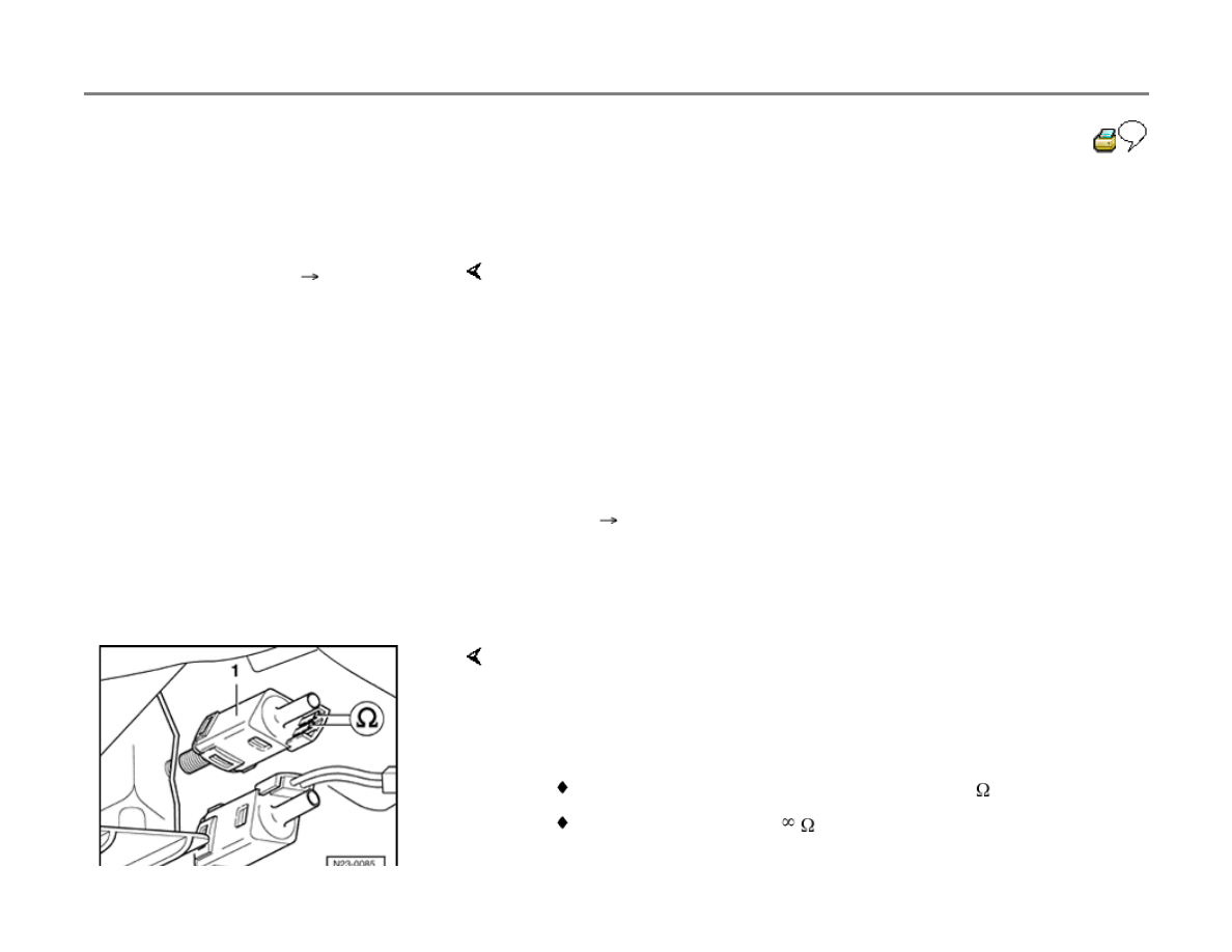
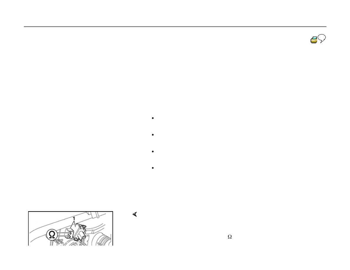
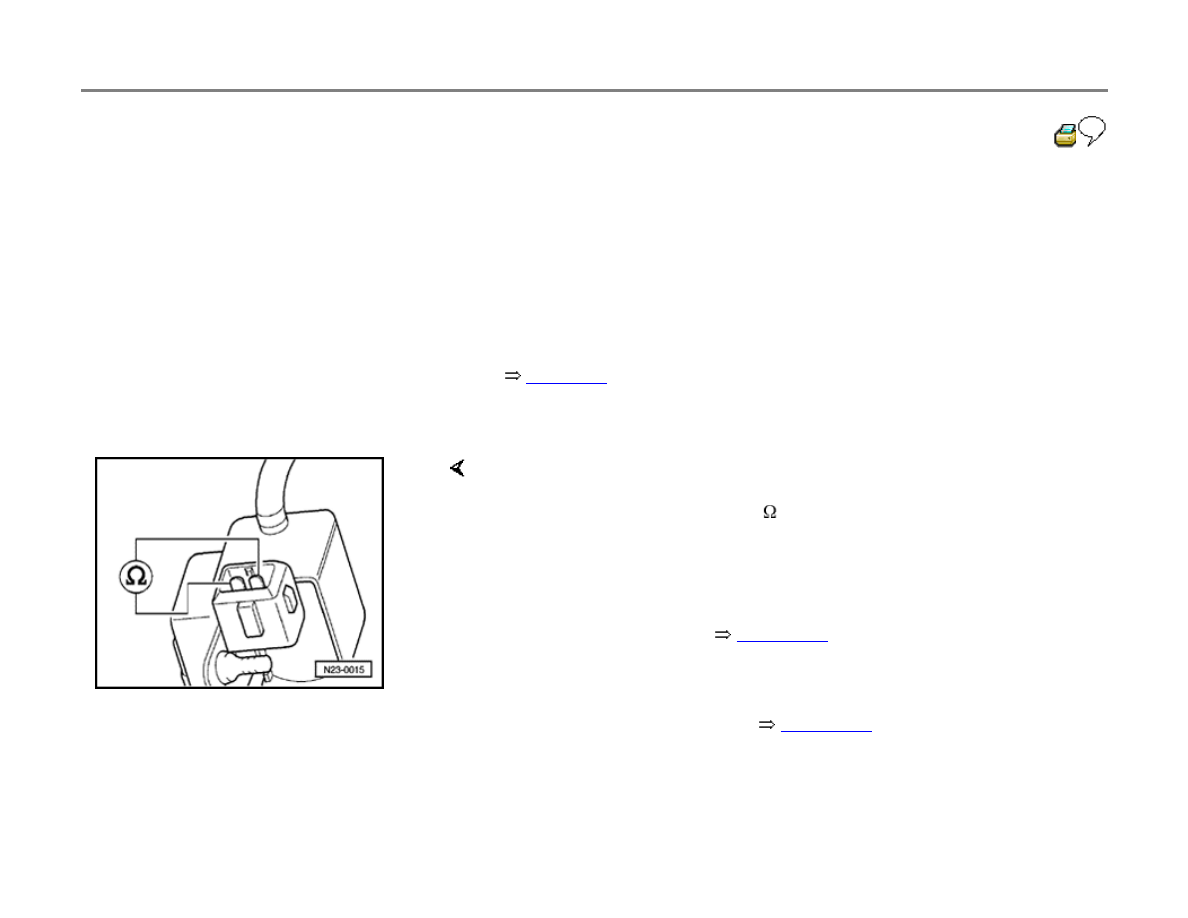
Wastegate bypass regulator valve, electrical
checks
- Switch ignition off.
- Disconnect wastegate bypass regulator valve
harness connector.
page 23-4
- Switch multimeter to resistance range.
If specification not obtained:
If DTC memory was erased:
- Connect multimeter between valve terminals and measure resistance.
Specification: 25 to 45 ohms ( )
- Replace wastegate bypass regulator valve -N75-.
- Display readiness code
page 01-43
.
- Create readiness code again
page 01-47
.
23-79
Wastegate bypass regulator valve -N75-
voltage supply, checking
- Switch ignition off.
- Disconnect wastegate bypass regulator valve
harness connector.
page 23-4
- Switch multimeter to 20 volt measurement
range.
If specification not obtained:
- Connect multimeter between terminal 1 and Ground using adapters
from VW1594 connector test kit.
- Switch ignition on.
Specification: approx. battery voltage (B+)
- Check wiring connection to wastegate bypass regulator valve -N75-.
- Switch ignition off.
- Connect VAG1598/18 test box to Diesel DFI ECM connector.
23-80
If neither an open nor short circuit exists:
If DTC memory was erased:
- Check wiring for open circuit between test box and 3-pin harness
connector, using wiring diagrams:
Terminal 1 and test box socket 68
Terminal 2 and test box socket 47
Wire resistance: max. 1.5 ohms (
)
- Check wiring for short circuit between connector terminals.
Specification:
(no continuity)
- Repair any open or short circuit as necessary.
- Replace Diesel DFI ECM -J248-
page 23-5
, item 17 .
- Display readiness code
page 01-43
.
- Create readiness code again
page 01-47
.
23-81
Exhaust Gas Recirculation (EGR) and
Mass Air Flow (MAF) sensor functions,
checking
Exhaust Gas Recirculation and Mass Air Flow
sensor function can be checked via Output
Diagnostic Test Mode (Function 03) and by also
calling-up measuring value block 03 (Function
08). To do this, activate the Output DTM
component: EGR Vacuum Regulator Solenoid
valve N18 and then after exiting the Output
Diagnostic Test Mode, check N18 via the -C-
button.
By using this sequence, the EGR valve continues
to be pulsed so that with the help of measuring
value block 03 (display field 3) the extreme
values for the EGR valve/Mass Air Flow sensor
can be displayed.
Special tools, testers and auxiliary items
VAG1551 or VAG1552 Scan Tool (ST)
VAG1551/3 adapter cable
VAG1598/18 test box

Multimeter (Fluke 83 or equivalent)
VW1594 connector test kit
Electrical Wiring Diagrams, Troubleshooting
& Component Locations binder
23-82
Checking
- Connect VAG1551 or VAG1552 scan tool.
page 01-9
- Start engine and let idle.
- Press buttons -0- and -1- to insert "Engine
Electronics" address word 01.
Rapid data transfer
HELP
Select function XX
Indicated on display
- Press buttons -0- and -3- to select "Output Diagnostic Test Mode"
function 03.
- Press -Q- button to confirm input.
Rapid data transfer
Q
03 - Output Diagnostic Test Mode
Indicated on display
Note:
Individual DTM components are activated for 30seconds. Various work
sequences must be carried out with the scan tool within this period as well
as reading the displayed values. Read over the following work sequence
first to familiarize yourself with the procedure.
Output Diagnostic Test Mode
Cold Start Injector-N108
Indicated on display

- Press
button.
Output Diagnostic Test Mode
Exhaust Gas Recirculation Valve-N18
Indicated on display
- Press -C- button.
23-83
- Press buttons -0- and -8- to select "Read
Measuring Value Block" function 08.
- Press -Q- button to confirm input.
Read Measuring Value Block
HELP
Input display group number XXX
Indicated on display
- Press buttons -0-, -0- and -3- to input display group no. 3 (003).
- Press -Q- button to confirm input.
Read Measuring Value Block 3
840 rpm 272 mg/H 268 mg/H 54 %
Note:
The values in display fields 3 and 4 must fluctuate within the following
control range:
- Indicated on display
Specification display field 3:
Lower range: 230-310 mg/stroke
Upper range: 360-480 mg/stroke
Specification display field 4:
Lower range: 2 to 5%
Upper range: 90 to 95%

Note:
Due to the slow refresh rate of the VAG1551 scan tool, the displayed
values can greatly vary. Ensure that the upper and lower range values in
display fields 3 and 4 are obtained. Only regard the minimum or maximum
values!
23-84
If specifications not obtained
- Check Mass Air Flow sensor and EGR valve
voltage supply as follows.
- Press
button.
- Press buttons -0- and -6- to select "End Output"
function 06.
- Press -Q- button to confirm input.
- Switch ignition off.
- Disconnrect harness connector -1- from Mass Air Flow sensor -2-
- Switch ignition on.
- Select 20 Volt measurement range
23-85
If specifications not obtained
- Perform voltage measurement using multimeter between following
connector terminals
Connector on terminal -G70-
Specification
3 and Ground
Battery voltage (approx)
3 and 5
Battery voltage (approx)
1 and Ground
Approx. 5 Volts
1 and 5
Approx. 5 Volts
- Switch ignition off.
- Connect VAG1598/18 test box to Diesel DFI ECM connector.
23-86
- Check wiring for open circuit between test box
and harness connector, using wiring diagrams:
Terminal 1 and test box socket 19
Terminal 2 and test box socket 33
Terminal 3 and test box socket 23
Terminal 5 and test box socket 1
Terminal 6 and test box socket 13
Wire resistance: max. 1.5 ohms (
)
- Check wiring for short circuit between connector
terminals.
Specification:
(no continuity)
If specifications obtained:
- Check EGR vacuum regulator solenoid valve
N18 as follows:

- Disconnect N18 valve harness connector.
page 23-5
, item 16
- Switch multimeter to resistance range.
23-87
If specification not obtained:
page 23-5
, item 16
If DTC memory was erased:
If specification obtained:
- Connect multimeter between valve terminals and measure resistance
Specification: 14 to 18 ohms ( )
- Replace EGR vacuum regulator solenoid valve -N18-
- Display readiness code
page 01-43
.
- Create readiness code again
page 01-47
.
- Switch ignition on.
If specification not obtained:
- Connect multimeter between connector terminal 1 and engine Ground
using adapters from VW1594 connector test kit.
Specification: approx. battery voltage
- Switch ignition off.
23-88
- Check wiring for open circuit/short to positive or
negative between test box and connector using
wiring diagrams.
Terminal 1 and test box socket 68
Terminal 2 and test box socket 25
Wire resistance: max. 1.5 ohms (
)
- Check wiring for short circuit between connector
terminals.
Specification:
(no continuity)
If wiring is OK:
- Replace Diesel DFI ECM -J248-
page 23-5
,
item 17 .
- Display readiness code
page 01-43
.
If DTC memory was erased:
- Create readiness code again
page 01-47
.

23-89
Vehicle speed signal, checking
Vehicle speed is required for A/C compressor
cut-off during acceleration, for the cruise control
system and to improve driving comfort (shift-
jerk).
Special tools, testers and auxiliary items
VAG1551 or VAG1552 Scan Tool (ST)
VAG1551/3 adapter cable
VAG1598/22 test box
VW1594 connector test kit
VAG1527B voltage tester
Electrical Wiring Diagrams, Troubleshooting
& Component Locations binder
Test conditions
Speedometer function and speedometer
display OK

Test sequence
- Connect VAG1551 or VAG1552 scan tool.
page 01-9
- Start engine and let idle.
23-90
- Press buttons -0- and -1- to insert the "Engine
Electronics" address word 01.
Rapid data transfer
HELP
Select function XX
Indicated on display
- Press buttons -0- and -8- to select "Read Measuring Value Block"
function 08.
- Press -Q- button to confirm input.
Read Measuring Value Block
HELP
Input display group number XXX
Indicated on display
- Press buttons -0-, -0- and -6- to input display group no. 6 (006).
- Press -Q- button to confirm input.
Read Measuring Value Block 6
1 2 3 4
Indicated on display (1 to 4
display fields)
CAUTION!
When "on the road" measurements are required for diagnosis, for
obvious safety reasons, always use a second technician to take the
instrument readings.
- Road test and observe display during drive.
- Check value in display field 1.
Specification: approx. equal to speedometer display
23-91
If there is no speed indicated:
- Switch ignition off.
If DTC memory was erased:
- Connect VAG1598/18 test box to Diesel DFI ECM connector.
- Check wiring for continuity or short circuit between test box socket 43
and instrument cluster wiring.
- Using wiring diagrams, individually determine all additional speed
signal "users" (e.g. radio, automatic transmission, A/C etc.), rule out
each one as a source of interference and repeat check each time until
cause has been established.
- Display readiness code
page 01-43
.
- Create readiness code again
page 01-47
.
23-92
Throttle Position (TP) sensor, checking
The throttle position sensor -G79- is located on
the accelerator pedal and transfers throttle
position information to the Diesel Direct Fuel
Injection (DFI) Engine Control Module (ECM).
Special tools, testers and auxiliary items
VAG1551 or VAG1552 Scan Tool (ST)
VAG1551/3 adapter cable
VAG1598/18 test box
VW1594 connector test kit
VAG1527B voltage tester
Multimeter (Fluke 83 or equivalent)
Electrical Wiring Diagrams, Troubleshooting
& Component Locations binder
Test sequence

- Connect VAG1551 or VAG1552 scan tool.
page 01-9
- Switch ignition on.
23-93
- Press buttons -0- and -1- to insert the "Engine
Electronics" address word 01.
Rapid data transfer
HELP
Select function XX
Indicated on display
- Press buttons -0- and -8- to select "Read Measuring Value Block"
function 08, and press -Q- button to confirm input.
Read Measuring Value Block
HELP
Input display group number XXX
Indicated on display
- Press buttons -0-, -0- and -2- to input display group no. 2 (002), and
press -Q- button to confirm input.
Read Measuring Value Block 2
RPM 0.0 % 0 1 0 18.4
C
- Refer to display field 2 (accelerator pedal position).
Specified display: 0.0 % (accelerator pedal not operated)
Read Measuring Value Block 2
RPM 0.0 % 0 1 0 18.4
C
- Refer to display field 3.
Specified display: 0 1 0 (accelerator pedal not operated)

23-94
- Press accelerator pedal down slowly.
Specified displays (accelerator pedal fully
depressed):
Read Measuring Value Block 2
RPM 100.0 % 0 0 0 18.4
C
Display field 2 must increase steadily to 100 %
Read Measuring Value Block 2
RPM 0.0 % 0 0 0 18.4
C
Note for vehicles with automatic transmission ONLY:
The kick down switch actuation point must be distinctly felt before the
pedal reaches Wide Open Throttle (WOT) position.
If the displays are not as specified:
page 23-16
If displays do not change or are irregular:
Display field 3 must change to: 0 0 0
- Adjust throttle position sensor.
- Check throttle position sensor -G79- as follows:
- Switch ignition off.
- Disconnect throttle position sensor harness connector.

page 23-4
- Switch multimeter to resistance range.
23-95
If resistance is not as specified:
If DTC memory was erased:
If specifications are obtained:
page 23-4
- Measure resistance between sensor terminals 1 and 3 using adapters
from VW1594 connector test kit.
Accelerator not depressed (closed throttle position):
Specification: 1000 to 1500 ohms (
)
Accelerator depressed (wide open throttle):
Specification: 1500 to 2500 ohms (
)
- Replace throttle position sensor -G79-.
- Display readiness code
page 01-43
.
- Create readiness code again
page 01-47
.
- Switch ignition off.
- Disconnect throttle position sensor harness connector.
- Connect VAG1598/18 test box to Diesel DFI ECM connector.
23-96
If neither an open or short circuit exists
If DTC memory was erased:
- Check following wiring connections for open circuits and/or short circuit
to positive or negative:
Terminal 1 to test box socket 15
Terminal 2 to test box socket 57
Terminal 3 to test box socket 55
Terminal 4 to test box socket 65
Terminal 5 to test box socket 62
Terminal 6 to test box socket 33
- Repair any open or short circuit as necessary.
- Replace Diesel DFI ECM -J248-
page 23-5
, item 17 .
- Display readiness code
page 01-43
.
- Create readiness code again
page 01-47
.
Wyszukiwarka
Podobne podstrony:
[Audi A4 TDI, Turbo] Diagnozowanie silnika TDI, Turbo
[Audi A4 B5 1 9 TDI AJM] Wymiana termostatu na przykładzie 1 9TDI PD AJM
[Audi A4 B6 TDI] Wymiana swiec zarowych 1 9 TDI AWX
[Audi A4 TDI] Jak interpretowac logi dynamiczne
[Audi A4 B6 TDI] Wymiana swiec zarowych 1 9 TDI AWX
[Audi A4 B5 1 9 TDI AJM] Wymiana termostatu na przykładzie 1 9TDI PD AJM
[Audi A4 TDI, TURBO] Zasady działania turbo, schemat, definicje, wykres
akumulator do audi a4 avant 8ed 19 tdi 20 tdi 20 tdi quattro
akumulator do audi a4 8e2b6 19 tdi 19 tdi quattro 25 tdi 25
akumulator do audi a4 cabriolet 8h7 25 tdi 25 v6 tdi s4 quatt
akumulator do audi a4 avant 8e2b6 19 tdi 19 tdi quattro 25 td
akumulator do audi a4 avant 8d5b5 19 tdi 19 tdi quattro 25 td
akumulator do audi a4 8ec 19 tdi 20 tdi 20 tdi quattro 20 td
akumulator do audi a4 8ec 25 tdi 27 tdi 30 tdi quattro
Audi A4 B7 Kasowanie wezwania do serwisu
[Audi A4 TDI] Jak interpretowac logi dynamiczne
akumulator do audi a4 avant 8ed 25 tdi 27 tdi 30 tdi quattro
akumulator do audi a4 8d2b5 19 tdi 19 tdi quattro 25 tdi 25
więcej podobnych podstron