C - Counter Relays of EASY500/700 Controllers
General
Note: Avoid unforeseeable switch states caused by incorrect program associations.
Only use each coil of a counter relay once in the circuit diagram.
When using "high-speed counters" the associated digital input I1, I2, I3 or I4 must not be used as a contact in the
circuit diagram at the same time.
If the counter frequency is > 1000 Hz only a random input value will be used in the circuit diagram.
Compatibility with EASY400 and EASY600
Function
A counter relay can be used both as a coil or as a contact (switch contact).
Activating the counter:
For starting, stopping, changing counting direction or resetting add the counter relay to your circuit diagram as a coil (in
the coil field). Then in the Coil function area define in which of these three functions, Count pulse, Count direction or
Reset, the coil is meant to operate.
Example:
A counter relay in normal operating mode, e.g. C01 receives count pulses via the count coil CC01 which has to be
linked. The count direction for this relay can also be modified by the DC01 direction coil which has to be linked. In this
case the following applies:
l
DC1 = 0: Relay C1 counts up
l
DC1 = 1: Relay C1 counts down
A third coil, the Reset coil RC01, can be used to reset the counter status to 0.
Switch function of the counter:
In order to process the result of the counter in the circuit diagram, the relay must operate as a switch. It must
therefore be added to the circuit diagram as a contact such as C01. In the Contact area of the Properties field, define
the function of the relay as a make or break contact.
If you only wish to display the result via the D - Text display function relay, the counter relay does not have to be
linked as a contact.
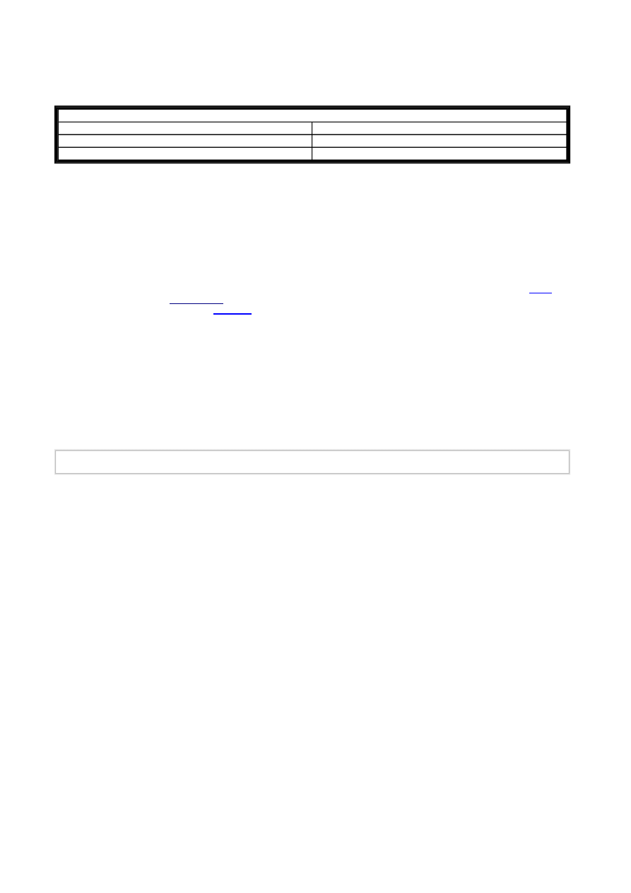
Can be used for
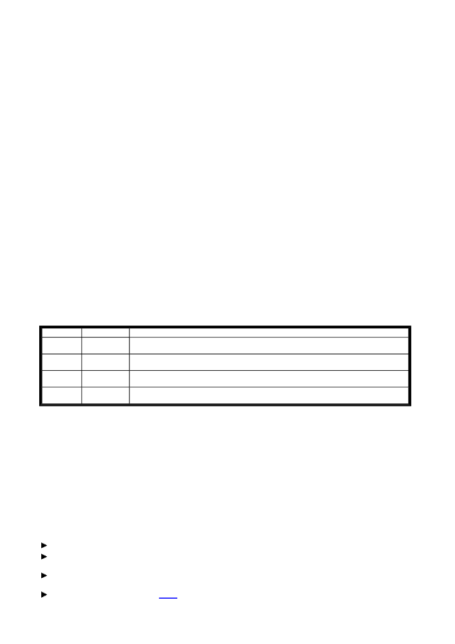
Device
From version no.:
EASY500
01
EASY700
01
The devices provide 16 up/down counter relays C01...C16.
A counter relay enables you to count events. The counter relay adds or subtracts pulses and switches when the actual
value is greater than or equal to the setpoint. You can define a setpoint between 0000 and 32000.
With the DA and DC versions of the devices you can also run two of these counter relays, C13/C14, as high-speed
counters. Two other counter relays, C15/C16, can also be used as high-speed frequency counters. Setting the
Mode
will
select one of the following
applications
described below.
Counter relays can be operated with
retentive
actual values.
The counter relays of an EASY500 or EASY700 operate in the same way as the counter relays of an EASY400 or
EASY600. If required, the same retentive counters can also be used.
Seite 1 von 8
C - Counter Relay_2
06.07.2005
file://X:\I\AA_Marketing_Services\Temp\Online%20Trainings%20Center\EASY-SO...
Applications
Use as a normal counter
The normal counters C01 - C12 and the C13 - C16 counters when used in Normal operating mode are cycle time
dependent. The maximum counter frequency therefore depends on the cycle time and thus on the length of the circuit
diagram (see Determining counter frequency).
25 Hz < fc < 200 Hz
Determining counter frequency:
The number of contacts, coils and circuit connections used determines the run time (cycle time) required to process the
circuit diagram.
When using EASY512-DC-TC with only three rungs for counting, resetting and outputting the result via the output, the
counter frequency may be 100 Hz.
To determine the cycle time refer to the manual.
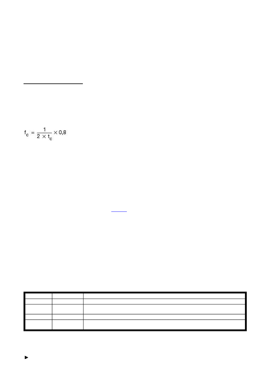
Use the following equation to determine the maximum counter frequency:
fc = maximum counter frequency [Hz] of the normal counters C01 - C12
tc = maximum cycle time [ms]
0.8 = Correction factor
Example of determining the maximum counter frequency:
The maximum cycle time is tc = 4000 µs (4 ms).
fc = 0.8*1/0.008s = 100 Hz
Linking and Parameter Assignment of a Normal Counter
Requirements:You have included a control relay in the project and have switched to Circuit Diagram View.
Note: Whether you position the function relay first of all in a coil field or contact field or whether you make the entries
in the Parameters tab of a coil or a contact is not important. It is only important that you have selected the same
function block number if you also want to configure the same function relay. For example, this is the case if you link the
function relay as a Counter coil or also as a Reset coil, so that the counter result can be reset.
You add a counter relay in your circuit diagram as a Counter coil (CC1 - CC16) and if required as a contact (C1 - C16).
You activate the count coil directly with the count signals that you take from the digital inputs or internal links.
With this counter application, you can control the count direction via the coils DC1 to DC16.
The result of the actual value setpoint comparison is only transferred once every program cycle for processing in the
circuit diagram.
The reaction time in relation to the setpoint/actual value comparison can therefore be up to one cycle.
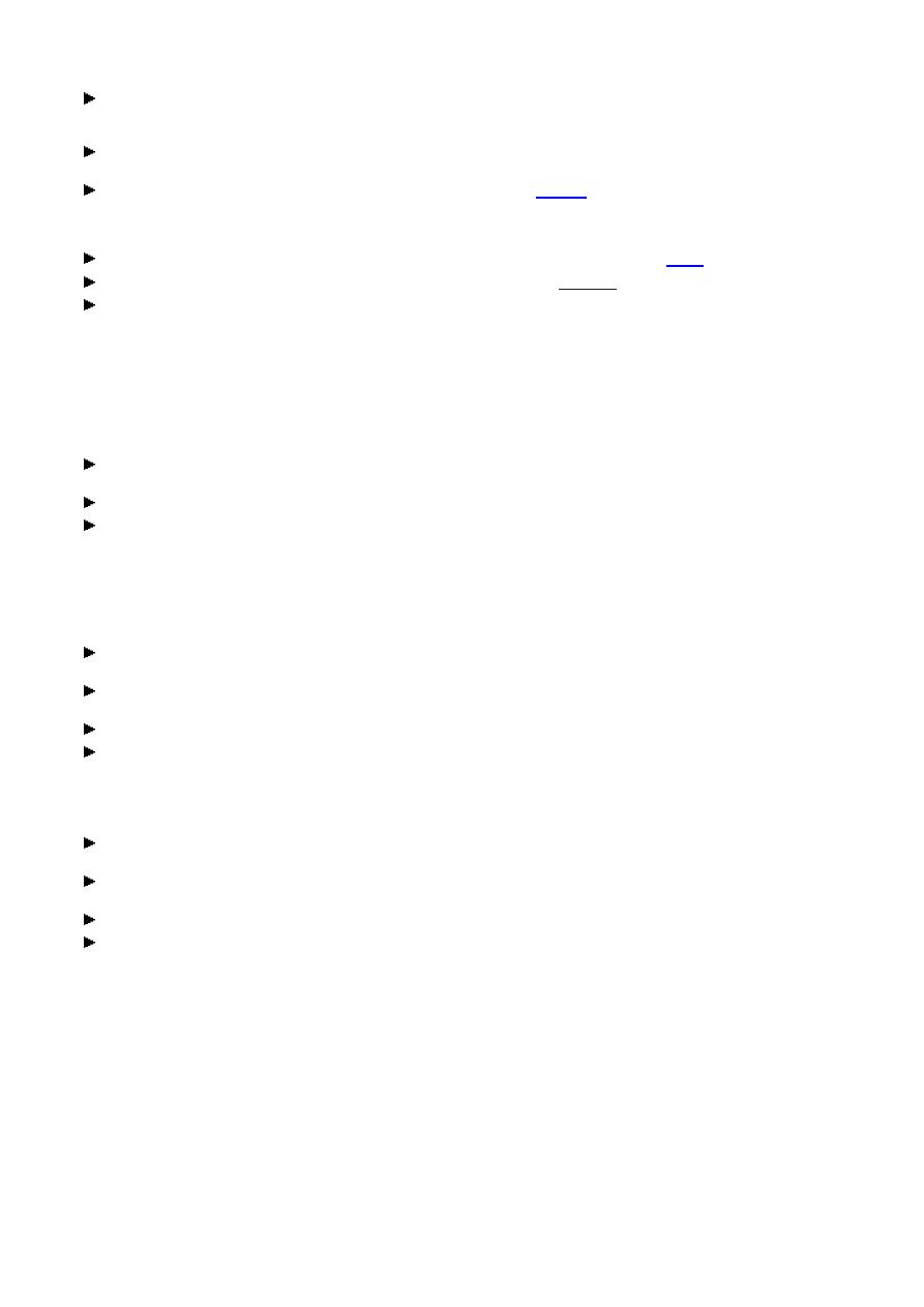
Contacts and coils of a counter relay in the Counter
Activating an up counter
Position a C counter relay operand in the circuit diagram on a coil field so that you can activate the count function.
Contact
Coil
Meaning
C01...C16
-
The contact switches if the actual value is greater than or equal to the setpoint.
-
CC01...CC16
Count coil(counter input)
Increment the counter in the configured direction on every rising edge
-
RC01...RC16
Reset of the actual value to zero on 1 signal
-
DC01...DC16
Count direction
Function: 0 = up counting, 1 = down counting
Seite 2 von 8
C - Counter Relay_2
06.07.2005
file://X:\I\AA_Marketing_Services\Temp\Online%20Trainings%20Center\EASY-SO...
In the Properties field window select the required function block number between 1 and 16 on the Circuit
Diagram Element tab. When using counters C1 - C12, the normal operating mode required here is activated
automatically.
In the Circuit Diagram Element tab select the Count pulse function required here in the Coil function area. The
operand CCxx will now be shown in the circuit diagram.
In the Parameters tab make the required parameter setting for the
setpoint
if you are not only displaying the
counter status but are also programming a switch operation that depends on this. Read the following section
Evaluation of a counter contact for further information.
You can use a constant, an analog input or the actual value of other function relays (C and T) as a setpoint.
If you used the counters C13 - C16, you must also select the Normal parameter in the
Mode
If necessary, change the enable of the parameter display and/or write a
comment
for the selected operand.
Connect the CCxx coil with an appropriate contact for triggering the counter function.
The counter relay counts up for as long it receives count pulses via the CCxx count coil and the count direction is
set to 0.
Evaluation of a counter contact
If you wish to trigger a switching operation when a particular counter status is reached, you must also position the CCx
operand that is programmed as a coil on a contact field. The contact switches if the actual value is greater than or equal
to the setpoint.
Position the function relay on a contact field and select the same function block number in the Circuit Diagram
Element tab that you have assigned to the coil.
If required, change the switch function of the contact from break to make contact.
Connect the Cxx contact with a suitable coil for evaluating the counter and comparison results.
Reversing the counter direction
If, for example, you wish to reverse the count direction and start counting down when a particular counter state is
reached, you have to trigger the count direction coil.
In order to reverse the count direction, position the C function relay that has already been linked as a counter coil
once more on a coil field of your circuit diagram.
In the Circuit Diagram Element tab select the function block number between 1 and 16 that has been used for
the up counting direction.
Also select the Count direction coil function. The operand DCxx will now be shown in the circuit diagram.
Connect the DCxx coil with an appropriate contact for triggering the count direction reversal.
The control relay counts down for as long as it receives count pulses via the CCxx count coil and the count direction
coil is set to 1.
Resetting a counter
In order to reset the counter status position the C function relay that has already been linked as a counter coil
once more on a coil field of your circuit diagram.
In the Circuit Diagram Element tab select the same function block number between 1 and 16 that has been used
for the counting operation.
Also select the Reset coil function. The operand RCxx will now be shown in the circuit diagram.
Connect the RCxx reset coil with an appropriate contact for triggering the Reset function.
The counter relay actual value is set to zero as soon as the Reset coil is set to 1.
Switching behaviour when reaching the value range
Requirement The control relay is in RUN mode. The CCx count coil receives count pulses and the RCxx Reset coil is
set to 0.
If the limit value of 32000 is reached, this value will be retained until the count direction is changed. If the value of
00000 is reached, this value will be retained until the count direction is changed.
The contact Cxx of the counter switches as soon as the actual value reaches the configured setpoint. If the count
direction is changed, the relay contact is reset if the actual value goes below the defined setpoint. The actual value will
be retained without any new count pulses.
Use as a high-speed counter
Seite 3 von 8
C - Counter Relay_2
06.07.2005
file://X:\I\AA_Marketing_Services\Temp\Online%20Trainings%20Center\EASY-SO...
The DA and DC versions of the device concerned offer users two high-speed counters C13 and C14. High-speed
counters operate independently of the cycle time.
Possible applications for high-speed counters:
Event, quantity and length data acquisition, and for frequency measurement.
The maximum counter frequency of the high-speed counters is 1000 Hz.Square wave signals must be used with a
mark-to-space ratio of 1.
Note: If this mark-to-space ratio cannot be ensured, the minimum mark or space duration must not go below tmin 0.5
ms.
The following therefore applies: tmin = 0.5 x (1/fmax)
tmin = minimum time of mark or space duration,
fmax = maximum counter frequency (1 kHz)
Linking and Parameter Assignment of a High-Speed Counter Relay
Requirements:You have included a control relay in the project and have switched to Circuit Diagram View.
You add a high-speed counter relay in your circuit diagram as a Counter enable coil (CC13/CC14) and, if required, as a
contact (CC13/CC14).
For high-speed counter applications you can control the count direction via the coils DC13 and DC14.
High-speed counters are permanently connected to digital inputs I1 and I2 with the following assignment:
l
I1 high-speed counter input for counter C13
l
I2 high-speed counter input for counter C14
The counter signals are transferred directly from the digital inputs to the counters.
The result of the actual value setpoint comparison is only transferred once every program cycle for processing in the
circuit diagram.
The reaction time in relation to the setpoint/actual value comparison can therefore be up to one cycle.
Contacts and coils of a counter relay in the High-Speed Counter function.
Activating a high-speed up counter
Position a C counter relay operand in the circuit diagram on a coil field so that you can activate the count function.
In the Properties field window select the required function block number 13 or 14 on the Circuit Diagram
Element tab.
In the Circuit Diagram Element tab select the Count pulse function required for the counter enable in the Coil
function area. The operand CCxx will now be shown in the circuit diagram.
Choose the Parameters tab and ,
Mode
list box, and select the High-speed parameter.
In the Parameters tab make the required parameter setting for the
setpoint
if you are not only displaying the
counter status but are also programming a switch operation that depends on this. Read the following section
Evaluation of a counter contact for further information.
You can use a constant, an analog input or the actual value of other function relays (C and T) as a setpoint.
If necessary, change the enable of the parameter display and/or write a
comment
for the selected operand.
Connect the CCxx coil with an appropriate contact for triggering the counter function.
When using C13, connect the encoder directly to the I1 digital input, and connect C14 to I2.
Contact
Coil
Meaning
C13,
C14
-
The contact switches if the actual value is greater than or equal to the setpoint.
-
CC13,
CC14
Enable of the high-speed counter on 1 signal
(coil activated)
-
RC13,
RC14
Reset of the actual value to zero on 1 signal
-
DC13,
DC14
Count direction
Function: 0 = up counting, 1 = down counting
Seite 4 von 8
C - Counter Relay_2
06.07.2005
file://X:\I\AA_Marketing_Services\Temp\Online%20Trainings%20Center\EASY-SO...
The counter relay counts up as long as:
l
it receives count pulses via the inputs I1 or I2,
l
the enable coil CCxx is set to 1,
l
the count direction coil DCxx is 0 and
l
the Reset coil RCxx is set to 0.
For simple up counting only the Enable coil has to be linked. Count direction and Reset coil can remain without an
association.
Evaluation of a counter contact
If you wish to trigger a switching operation when a particular counter status is reached, you must also position the CCx
operand that is programmed as a coil on a contact field. The contact switches if the actual value is greater than or equal
to the setpoint.
Position the function relay on a contact field and select the same function block number in the Circuit Diagram
Element tab that you have assigned to the coil.
Connect the Cxx contact with a suitable coil for evaluating the counter and comparison results.
Reversing the counter direction
If you wish to reverse the count direction of a coil you must activate the count direction coil.
In order to reverse the count direction position the C function relay that has already been linked as an Enable coil
once more on a coil field of your circuit diagram.
In the Circuit Diagram Element tab select the same function block number 13 or 14 that has been used for the up
counting direction.
Also select the Count direction coil function. The operand DCxx will now be shown in the circuit diagram.
Connect the DCxx coil with an appropriate contact for triggering the count direction reversal.
The control relay counts down for as long as it receives count pulses via the CCxx count coil and the count direction
coil is set to 1.
Resetting a counter
In order to reset the counter status position the C function relay that has already been linked as an enable coil
once more on a coil field of your circuit diagram.
In the Circuit Diagram Element tab select the same function block number 13 or 14 that has been used for the
count operation.
Also select the Reset coil function. The operand RCxx will now be shown in the circuit diagram.
Connect the RCxx reset coil with an appropriate contact for triggering the Reset function.
The counter relay actual value is set to zero as soon as the Reset coil is set to 1.
Switching behaviour when reaching the value range
Requirement: The control relay is in RUN mode. The enable coil CCx is set to 1 and the reset coil RCx is set to 0.
The relay contact C13 (14) of the counter switches as soon as the actual value reaches the configured setpoint. If the
count direction is changed, the relay contact is reset if the actual value goes below the defined setpoint.
When new count pulses or the counter enable via CC13 (14) are not present, the actual value is retained.
If the limit value of 32000 is reached, this value will be retained until the count direction is changed. If the value of
00000 is reached, this value will be retained until the count direction is changed.
Use as a frequency counter
The DA and DC versions of the device concerned offer users two frequency counters C15 and C16. Frequency counters
operate independently of the cycle time.
Frequency counters C15 and C16 can be used for determining motor speeds, volume measurement using volume
meters or the running of a motor.
Counter frequency and pulse shape
Seite 5 von 8
C - Counter Relay_2
06.07.2005
file://X:\I\AA_Marketing_Services\Temp\Online%20Trainings%20Center\EASY-SO...
The minimum counter frequency of the frequency counters is 4 Hz and the maximum counter frequency is 1000 Hz.
4 Hz < fc < 1000 Hz
Square wave signals must be used with a mark-to-space ratio of 1.
Note: If this mark-to-space ratio cannot be ensured, the minimum mark or space duration must not go below tmin 0.5
ms.
The following therefore applies: tmin = 0.5 x (1/fmax)
tmin = minimum time of mark or space duration,
fmax = maximum counter frequency (1 kHz)
Measuring procedure
The pulses at the input are counted for one second, irrespective of the cycle time, and the frequency determined.
The measurement result is provided as an actual value.
The result of the actual value setpoint comparison is only transferred once every program cycle for processing in the
circuit diagram.
The reaction time in relation to the setpoint/actual value comparison can therefore be up to one cycle.
Linking and Parameter Assignment of a Frequency Counter
Requirements:You have included a control relay in the project and have switched to Circuit Diagram View.
You add a frequency counter in your circuit diagram as a counter enable coil (CC15/CC16) and, if required, as a contact
(CC15/CC16).
Coils DC15 and DC16 have no meaning when frequency counters are used.
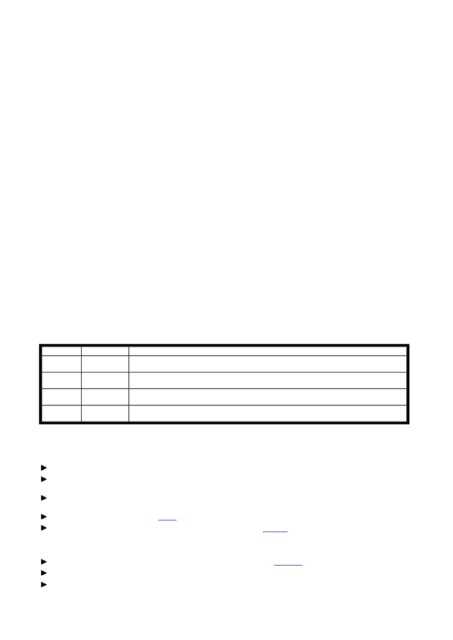
Contacts and coils of a counter relay used as a frequency counter
Frequency counters are permanently connected to digital inputs I3 and I4 with the following assignment:
l
I3 counter input for frequency counter C15
l
I4 counter input for frequency counter C16
The counter signals are transferred directly from the digital inputs to the counters. A frequency counter measures the
actual value.
The result of the actual value setpoint comparison is only transferred once every program cycle for processing in the
circuit diagram.
The reaction time in relation to the setpoint/actual value comparison can therefore be up to one cycle.
Activating a frequency counter
Position a C counter relay operand in the circuit diagram on a coil field so that you can activate the count function.
In the Properties field window select the required function block number 15 or 16 on the Circuit Diagram
Element tab.
In the Circuit Diagram Element tab select the Count pulse function required for the counter enable in the Coil
function area. The operand CCxx will now be shown in the circuit diagram.
Choose the Parameters tab and ,
Mode
list box, and select the Frequency parameter.
Contact
Coil
Meaning
C15,
C16
-
The contact switches if the actual value is greater than or equal to the setpoint.
-
CC15,
CC16
Enable of the frequency counter on 1 signal
(coil activated)
-
RC15,
RC16
Reset of the actual value to zero on 1 signal
-
DC15,
DC16
No function
Seite 6 von 8
C - Counter Relay_2
06.07.2005
file://X:\I\AA_Marketing_Services\Temp\Online%20Trainings%20Center\EASY-SO...
In the Parameters tab make the required parameter setting for the
setpoint
if you are not only displaying the
counter status but are also programming a switch operation that depends on this. Read the following section
Evaluation of a counter contact for further information.
You can use a constant, an analog input or the actual value of other function relays (C and T) as a setpoint.
If necessary, change the enable of the parameter display and/or write a
comment
for the selected operand.
Connect the CCxx coil with an appropriate contact for enabling the frequency counter.
Note: An activated frequency counter increases the cycle time of the device and therefore reduces the speed at which
the circuit diagram is processed. Only enable frequency measurement in those phases of processing in which you
actually wish to process the measured value.
When using C15, connect the encoder directly to the I3 digital input, and connect C16 to I4.
The frequency counter will provide a measured value as long as:
l
it receives count pulses via the inputs I3 or I4,
l
the enable coil CCxx is set to 1 and
l
the Reset coil RCxx is set to 0.
When only frequency measurement is required, you only have to link the enable coil. The reset coil can be left
unassigned.
Evaluation of a counter contact
If you wish to trigger a switching operation when a particular frequency is reached, you must position the CCxx
operand that is programmed as a coil also on a contact field. The contact switches if the actual value is greater than or
equal to the setpoint.
Position the function relay on a contact field and select the same function block number in the Circuit Diagram
Element tab that you have assigned to the coil.
Connect the Cxx contact with a suitable coil for evaluating the counter and comparison results.
Switching behaviour when reaching the setpoint
Requirement: The control relay is in RUN mode. The enable coil CCx is set to 1 and the reset coil RCx is set to 0.
Once a frequency higher than the configured setpoint is measured for the first time, the associated contact C15 (16)
will switch to 1. If the frequency then goes below the setpoint, the contact is reset to 0. Removing the enable signal will
reset the actual value to zero and the contact C15 (16) will switch to 0.
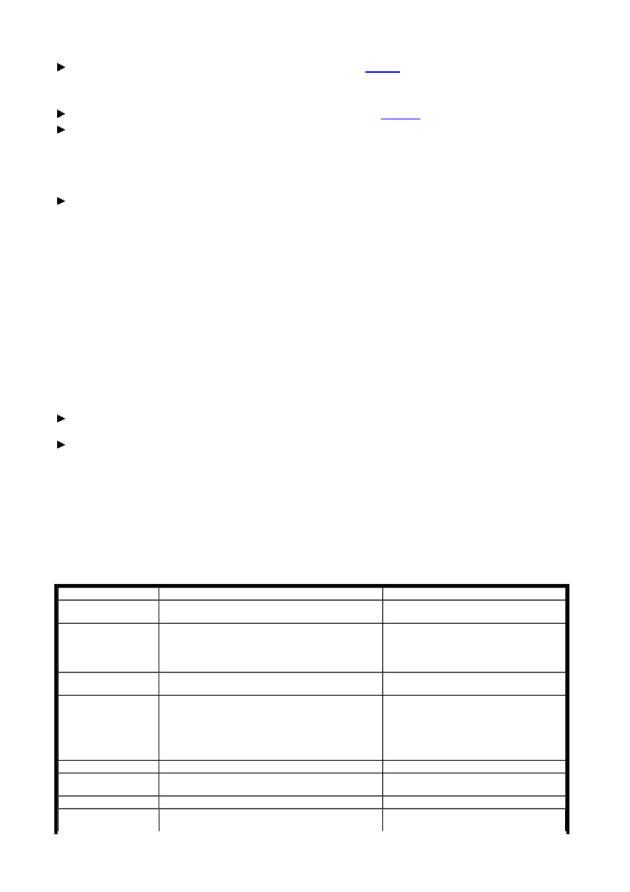
Circuit diagram elements and parameters
Description
Note
Function relay
input
Setpoint
The function block operates in the integer range
from 0 to +32000.
The value only has to be entered once,
even if you use the counter relay in
the circuit diagram both as a coil and
a contact.
Function relay
output
C
Integer value from 0...+32000
This output can be used as a setpoint for the T
timing relay, other C counter relays and the A
analog value comparator as well as an actual
value for the D text display.
Contact
Cxx
Status 1 if the actual value is greater than or
equal to the setpoint.
Coil function
Designation
Count pulse/
Count coil
CCxx
Seite 7 von 8
C - Counter Relay_2
06.07.2005
file://X:\I\AA_Marketing_Services\Temp\Online%20Trainings%20Center\EASY-SO...
Operand Selection for Setpoint Definition
Retention
Selected timing relays can be run with retentive actual values. If a counter relay is retentive, the actual value is
retained when the operating mode is changed from RUN to STOP and when the power supply is switched off. When the
control relay is restarted in RUN mode, the counter relay continues with the retentively stored actual value.
In Project View, select in the
System
tab which of the counter relays C5 to C7, C8 and C13 to C16 are to be kept
retentive.
The retentive actual value requires 4 bytes of memory.
Tip: Refer to the EASY500/700 manual (AWB 2528-1508x) for more information on the function block (e.g. signal
diagram).
enable coil
Function with normal counter: counts with
every rising edge in the set direction.
Function with high-speed/frequency counter:
Enable coil
Count direction
Count direction indication for "normal and high-
speed counter" modes.
Function: 0 = up counting, 1 = down counting
DCxx
Reset
Reset coil function: Reset of the actual value to
zero on 1 signal
RCxx
Mode
Normal
Up/down counter:
The
maximum pulse measurement
depends on
the length of the circuit diagram.
Counter C01...C12 via any inputs or
links
High-speed
High-speed up/down counter:
Pulse measurement up to 1000 Hz
Counters C13...C14 via the inputs I1
and I2 of the DA and DC versions
Frequency
Frequency counter:
Pulse measurement/s up to 1000 Hz
Counters C15...C16 via the inputs I3
and I4 of the DA and DC versions
Parameter
display
Call enabled
Function block parameters can be viewed on the
device.
Simulation
-
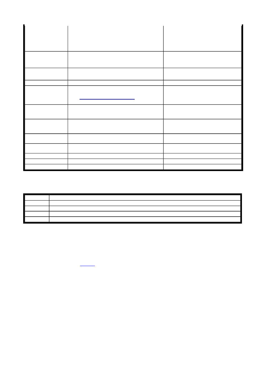
Operand
Description
Constant
0 ... 32000
C
Output of a counter relay (e.g. C3QV)
IA
Analog input of the device (I7 = IA1, I8 = IA2, I11 = IA3, I12 = IA4), if available
T
Output of a timing relay (e.g. T4QV)
Seite 8 von 8
C - Counter Relay_2
06.07.2005
file://X:\I\AA_Marketing_Services\Temp\Online%20Trainings%20Center\EASY-SO...
Wyszukiwarka
Podobne podstrony:
easy500 timing relay HLP EN
easy500 timing relay HLP EN
easy500 Master reset HLP EN
easy500 Text display HLP EN
easy500 Analog Comparator HLP EN
easy500 700 Operating hours counter HLP EN
easy500 Year time switch HLP EN
easy500 700 7 day time switch HLP EN
easy500 Jump HLP EN
easy500 Year time switch HLP EN
więcej podobnych podstron